Machining method for high-precision straight outline ring surface worm gear pair

A processing method and high-precision technology, applied in the direction of worms, worm wheels, and components with teeth, etc., can solve the problems of difficult control of the blade clearance, hindering the worm from entering the correct position, and inconvenient processing and installation, so as to facilitate industrialization. Significant strategic significance, the effect of improving processing efficiency

Inactive Publication Date: 2014-01-08
GUIZHOU CEC ZHENHUA PRECISION MACHINERY
View PDF7 Cites 6 Cited by
  • Summary
  • Abstract
  • Description
  • Claims
  • Application Information

AI Technical Summary

Problems solved by technology

In particular, the "knife-to-knife" processing technology proposed by Chongqing Machine Tool in 1985, that is, the "tilted knife-to-knife" processing method, but this technology only uses the approximate rough machining process of flying knife for the processing of worm gears, and the tooth shape error is relatively small. Large, the error not only affects the transmission accuracy, but also prevents the worm from entering the correct position during assembly. Due to the difficulty of assembly, the current accuracy is far below the third-level accuracy level when the first prize of the National Science and Technology Progress Award was awarded in 1985 (the original reference standard JB162 -60, now refer to the standard GB10089-88)
[0006] Due to the above method, the process is very complicated, and the processing and installation are also very inconvenient. It is difficult to control the gap between the blades, and it is difficult to process a high-precision straight-profile toroidal worm pair, which affects the technological progress of my country's basic core components.

Method used


Image

  • Machining method for high-precision straight outline ring surface worm gear pair
  • Machining method for high-precision straight outline ring surface worm gear pair
  • Machining method for high-precision straight outline ring surface worm gear pair

Examples


Embodiment Construction

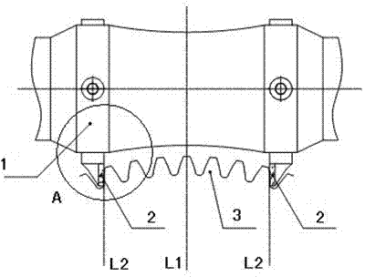
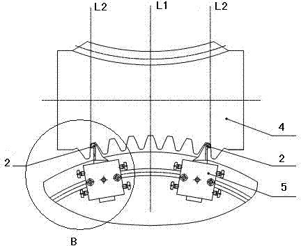
[0035] figure 1 It is a schematic diagram of the worm gear processing method. The worm gear machine is used for processing. First, the flying knife process is used for rough machining, and then the finish machining is performed after the gear cutting is completed. During finishing machining, two straight-edged cutters 2 (long blades) with the same tooth shape are installed on the tool bar 1 of the worm gear master machine. The blades are inlaid with carbide blades, and the straight-profile toroidal worm gear 3 to be processed is installed on the workbench. superior.

[0036] When machining the straight-profile toroidal worm gear 3, its end face and outer circle are calibrated, and then accurately installed on the workbench of the worm gear master machine, and then the tool bar 1 is installed on the tool holder of the worm gear master machine, and the straight-edged cutter 2 is adjusted according to the required distance Put the size into the holes at both ends of the tool bar...


PUM


Abstract

The invention discloses a machining method for a high-precision straight outline ring surface worm gear pair, and the machining method includes worm wheel (3) machining and worm (4) machining. In the machining process, two straight blade cutters (2) with the same tooth shape as that of (a worm wheel or a worm) are adopted, the cutting blade directions of the two straight blade cutters (2) are both parallel to the meshing center line of the straight outline ring surface worm wheel (3) and the worm (4) and are in cooperation with a dynamic testing instrument for monitoring error conditions in the cutting process, and segmented feeding is adopted when the worm (4) is machined. The machining method is simple in technology, the worm wheel and the worm can be simultaneously machined on different machine tools, so that machining efficiency and indexing accuracy are high, the straight outline ring surface worm gear pair with two or more ends can be machined, machining efficiency of the products can be multipled, urgent needs of the high-precision indexing mechanical transmission field in the machine tool industry in china can be met, and the machining method for the high-precision straight outline ring surface worm gear pair is of great strategic significance.

Description

technical field [0001] The invention relates to a processing method of a worm pair, in particular to a processing method of a high-precision straight-profile toroidal worm pair with precision indexing transmission. Background technique [0002] Due to the large number of meshing teeth of the straight-profile toroidal worm pair, compared with the existing cylindrical worm pair, it has significant advantages such as high transmission efficiency, good precision retention, long life, and high load-bearing capacity, so it is widely used in mines, aviation, automobiles, ships and It is widely used in the transmission of heavy machinery such as steel rolling. It is precisely because of the high load-carrying capacity of the straight-profile toroidal worm pair that it can be used for heavy-duty transmission. If the precision indexing transmission can be solved, the straight-profile toroidal worm pair will have a major application breakthrough. Therefore, how to process a high-precis...

Claims


Application Information

Patent Timeline
Patent Type & Authority Applications(China)
IPC IPC(8): B23F11/00B23F13/00
Inventor 查谦查世樑章根国丁晓鸿付贤民郑晓纯
Owner GUIZHOU CEC ZHENHUA PRECISION MACHINERY
Why Eureka
Try Eureka