Gear processing technology

A processing technology and gear technology, applied in the field of gear processing technology, can solve the problems of poor ability to overcome axial force, many factors of processing quality, slow workpiece clamping speed, etc., and achieve enhanced ability of reciprocating axial force , The cost saving of the full tooth pitch circular fixture and the effect of increasing the clamping speed of the workpiece

Active Publication Date: 2014-01-08
WUHU WANLIYANG TRANSMISSION CO LTD
View PDF9 Cites 12 Cited by
  • Summary
  • Abstract
  • Description
  • Claims
  • Application Information

AI Technical Summary

Problems solved by technology

[0006] 1. There are many factors affecting the processing quality during clamping and processing, and the quality stability of the ring gear beating and the tooth direction is poor
[0007] The positioning and clamping of the gear is realized by the contact between the drum-shaped cylinder on the pitch circle fixture and the tooth surface of the gear tooth. In mass production, the operator is required to put the contact with the tooth surface It is indeed very difficult to clean each drum-shaped cylinder very clean. Therefore, sometimes the phenomenon that the drum-shaped cylinder contacts the tooth surface and pads the grinding wheel powder occurs, resulting in a large jump of the ring gear after processing, which leads to the scrapping of the workpiece; and When grinding helical gears, the tooth surfaces are all helical surfaces and most of the gears require a drum-shaped amount in the tooth direction. In addition, the drum-shaped cylinder of the full-pitch circular fixture is basically in point contact with the tooth surface, so this kind of The clamping method has poor ability to overcome axial force
During the processing, the gear is subjected to continuous reciprocating axial force, so it is more likely that the gear

Method used


Image

  • Gear processing technology
  • Gear processing technology
  • Gear processing technology

Examples


specific Embodiment

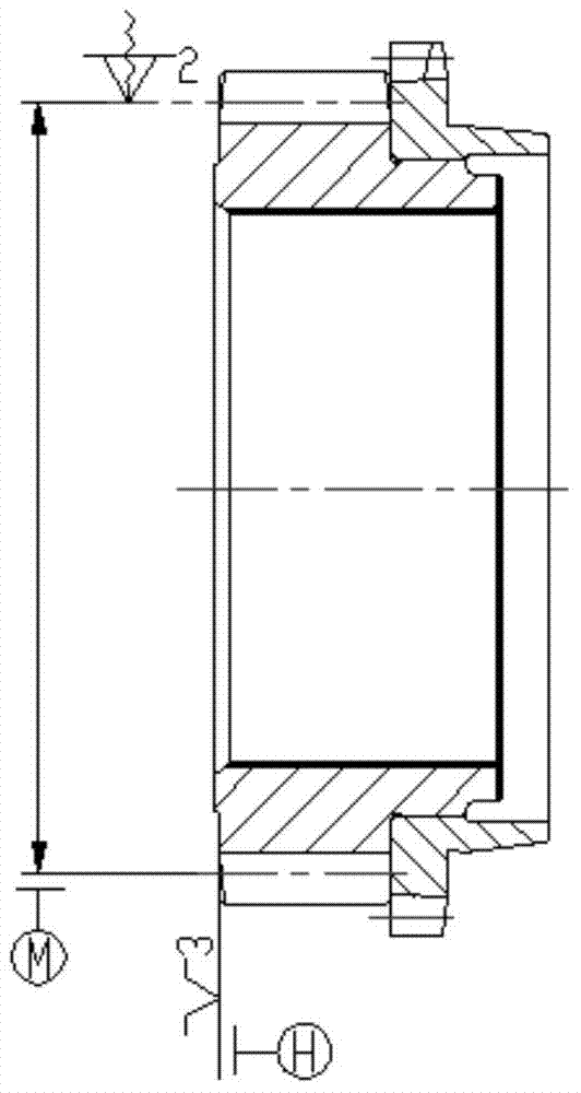
[0044] It is not difficult to find out by analyzing the prior art that the generation of these problems in the prior art is related to the full pitch circle clamp. Therefore, the present invention improves the positioning and clamping methods of process 10 grinding inner hole and end face process in the prior art, cancels the full pitch circle fixture, and adopts the method of directly clamping the tooth top reference circle with the film clamp jaw to replace the full pitch circle fixture. The specific embodiment process is as follows:

[0045] The invention provides a gear processing technology, which is carried out according to the following procedures,

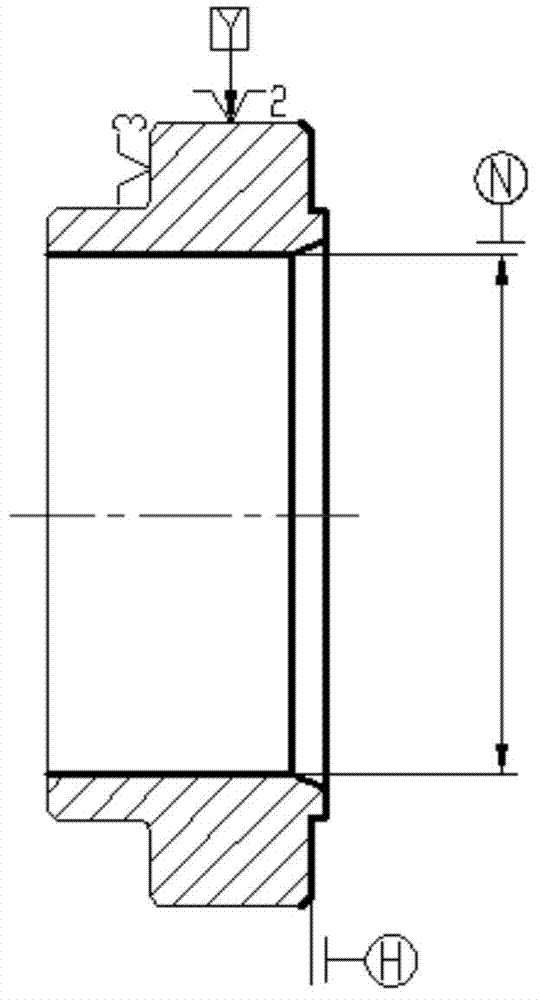
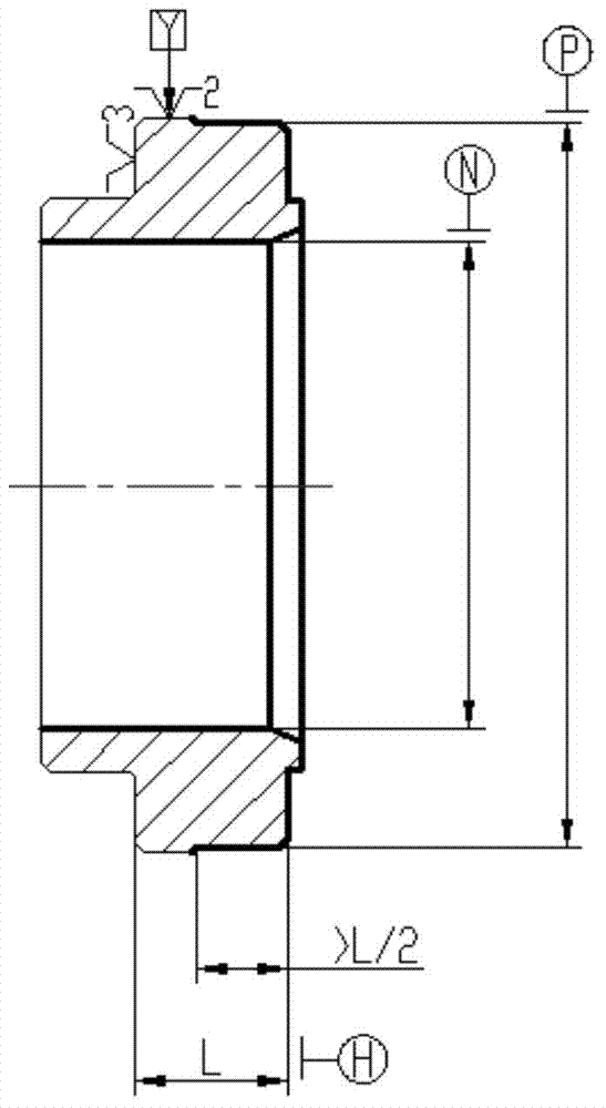
[0046] Process 1, car one, specifically the car out of the reference hole, reference end face and reference circle, in this embodiment, in process 1, car one, such as figure 2 As shown, it is a schematic diagram of process 1 turning and process provided by the present invention. In one clamping, when the reference hole N...


PUM


Abstract

The invention discloses a gear processing technology, and belongs to the field of mechanical manufacturing. According to the gear processing technology, a tooth crest basic circle P turned in the first process provides a reliable positioning and clamping replacing standard for machining after heating, and therefore a workpiece can be positioned and clamped reliably, the workpiece is convenient to clamp, and the quality of gears is more stable. A film clamping claw directly clamps the tooth crest basic circle P, compared with an original method, the clamping method has the advantages that the capability to overcome the reciprocating axial acting force is obviously enhanced, the effect of grinding wheel powder on machining quality is reduced in the positioning and clamping process, the phenomenon that because of abrasion and deformation of drum-shaped cylinders on a full pitch circle clamp, relevant machining quality is affected is thoroughly eliminated, and therefore the machining quality of the gears can be stable. Besides, the rejection rate is reduced, the clamping speed of the workpiece is increased, cost of the full pitch circle clamp is saved, and machining cost of the gears is lowered correspondingly.

Description

technical field [0001] The invention relates to the field of mechanical manufacturing, in particular to a gear processing technology. Background technique [0002] Gear machining processes are extremely common in the field of machine building. Let's take a gear in the automobile manual transmission assembly as an example to illustrate the processing technology of the gear, including the following procedures: [0003] Process 1, car one; process 2, car two; process 3, hobbing; process 4, chamfering; process 5, shaving; process 6, cleaning; process 7, pressing; process 8, welding; process 9, heat treatment ; Process 10, grinding the inner hole and end face; process 11, grinding the other end face; process 12, grinding the cone surface; process 13, polishing the cone surface; process 14, cleaning, transfer assembly. [0004] In the above process, if figure 1 Shown is a schematic diagram of the first process of the car in the prior art. The first process of the car is only to...

Claims


Application Information

Patent Timeline
IPC IPC(8): B23P15/14
CPCB23P15/14
Inventor 梁振东翟丽文芳芳
Owner WUHU WANLIYANG TRANSMISSION CO LTD
Why Eureka
Try Eureka