
Roller-hearth type creeper tread quenching press machine

A technology for quenching presses and track shoes, which is applied in furnaces, heat treatment equipment, heat treatment furnaces, etc., and can solve the problems of high critical cooling speed, large volume, and quenching failure.

Inactive Publication Date: 2014-01-08
SHANDONG JIANZHU UNIV
View PDF7 Cites 6 Cited by
  • Summary
  • Abstract
  • Description
  • Claims
  • Application Information

AI Technical Summary

Problems solved by technology

[0005] Track shoes are mostly made of low-carbon alloy structural steel. The critical cooling rate of martensitic transformation of this kind of material is very high. It must be cooled from Ac3 to the martensitic transformation temperature of about 350°C within a few seconds, otherwise it will lead to quenching failure. , in order to ensure that the number of rollers passed by the track shoe in the interval from Ms to Mf is as large as possible, it is necessary to have a higher corrected rolling speed, resulting in large equipment volume and high cost
During the quenching and cooling process of the track shoes, the correction force required is increasing as the temperature decreases, and the rolling driving force required for the increase of the roller pressure is also large, the stress condition of the roller is deteriorated, and the energy consumption is high
[0006] Another method is to use a manipulator to grab the high-temperature workpiece out of the furnace to the press quenching machine for press quenching. The requirements for the press quenching and grabbing equipment are high, and the equipment cost is high. If a single manipulator is used for operation, it takes a long time and the efficiency is low.

Method used


Image

  • Roller-hearth type creeper tread quenching press machine
  • Roller-hearth type creeper tread quenching press machine
  • Roller-hearth type creeper tread quenching press machine

Examples


Embodiment Construction

[0034] In order to clearly illustrate the technical characteristics of this solution, the following will describe this solution through specific implementation modes and in conjunction with the accompanying drawings.

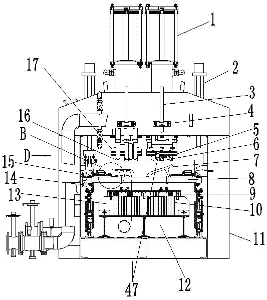
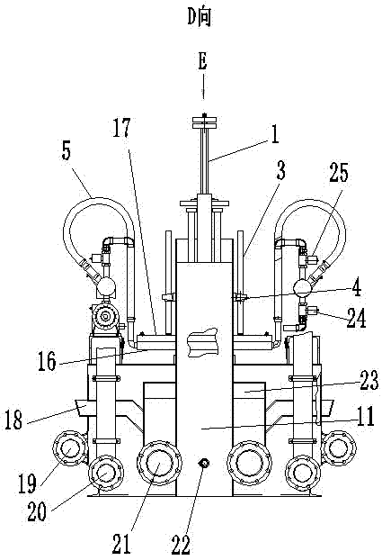
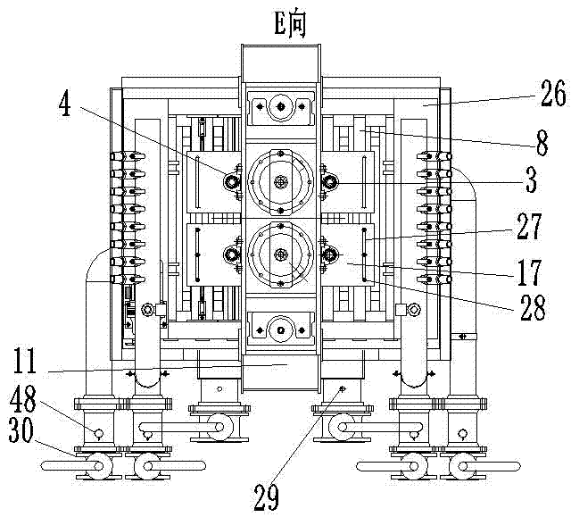
[0035]A roller bottom track shoe quenching press, as shown in the figure, it includes a frame, above which a drive roller 8 that can reciprocate up and down is installed, and the two ends of the drive roller 8 are installed on a floating bracket 26, Ten transmission rollers 8 are installed on the preferred floating support 26, the gap between adjacent transmission rollers 8 is 130-150mm, preferably 142mm, the same end of each transmission roller 8 is equipped with a roller sprocket 14, and is located in the feeding The first drive roller 8 at the end is equipped with two sprockets, one of which is used to access the motor power, that is, the drive sprocket 15, and the other sprocket is a roller sprocket 14, which is connected with the rest of the drive rollers. ...


PUM


Abstract

The invention provides a roller-hearth type creeper tread quenching press machine. The roller-hearth type creeper tread quenching press machine comprises a rack, wherein a driving roller which can reciprocate up and down is arranged above the rack, at least two rows of guide grooves are formed in the driving roller, press quenching upper molds corresponding to the guide grooves in the terms of number and location are arranged above the driving roller and are driven by a power device to reciprocate up and down, press quenching lower molds which correspond to the press quenching upper molds and are fixed are arranged below the driving roller, and the driving roller and the press quenching lower molds are arranged at intervals; the press quenching upper molds comprise upper mold plates and upper mold pressure feet which are connected to lower planes of the upper mold plates, the number of the upper mold pressure feet is at least two, the upper mold pressure feet are sequentially arranged along the axial direction of the driving roller, the distance between the adjacent upper mold pressure feed can be adjusted, the locations of the upper mold pressure feet can be flexibly adjusted according to different types of creeper treads along the direction of the driving roller, so that the upper mold pressure feet are pressed right above teeth of the creeper tread so as to prevent the creeper tread from deforming under the pressure of the upper mold pressure feet, thus the quenching quality of the creeper tread is improved.

Description

technical field [0001] The invention relates to a quenching press, in particular to a roller bottom type track shoe quenching press. Background technique [0002] The quenching process of the track shoe heat treatment production line for construction machinery is usually operated by online rolling quenching. Springs or cylinders are used to provide rolling quenching pressure and at the same time provide rotational driving force for track shoe support rollers. The rolling quenching pressure is small. The track shoe is supported by multiple points along the length of the track shoe, and the residual deformation of the track shoe is large. After quenching and tempering, the proportion of the track shoe that still needs to be corrected is large, the cost is high, and the efficiency is low. [0003] For shorter track shoes, in order to ensure the rigidity of the correction rollers, it is impossible to arrange a large number of correction rollers engaged along the length of the tr...

Claims


Application Information

Patent Timeline
IPC IPC(8): C21D9/00C21D1/18
Inventor 王献忠孙清州孙德明张保议徐勇王志刚李永胜吴俊平
Owner SHANDONG JIANZHU UNIV
Learn More