Exhaust steam recycling heating device for waste heat power generation deaerator

A technology of waste heat power generation and heating device, which is applied in chemical instruments and methods, liquid degassing, separation methods, etc., can solve problems such as poor thermal economy, and achieve the effects of small vibration, improved energy utilization, and low price.

Inactive Publication Date: 2014-01-08
JINAN AOHAI CARBON PROD
View PDF6 Cites 13 Cited by
  • Summary
  • Abstract
  • Description
  • Claims
  • Application Information

AI Technical Summary

Problems solved by technology

[0004] In order to overcome the disadvantage of poor thermal economy of the existing deaerator exhaust gas recovery system, the present invention provides a waste heat power generation deaerator exhaust gas recovery heating device

Method used


Image

  • Exhaust steam recycling heating device for waste heat power generation deaerator

Examples


Embodiment 1

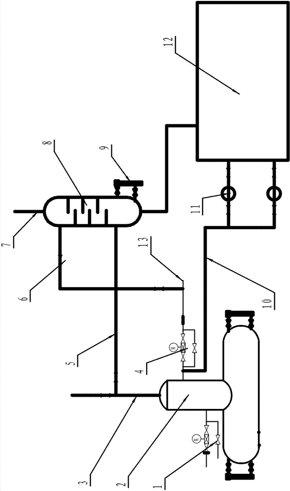
[0035] Example 1, a waste heat power generation deaerator exhaust steam recovery heating device, including a deaerator 2, the deaerator is connected to the steam pipeline through the deaerator inlet valve 1 with a steam flow meter, and the top of the deaerator is equipped with The deoxygenation exhaust pipe 3 with valve is characterized in that: the valve of the deoxygenation exhaust pipe is provided with a deaerator exhaust pipe 5 connected to the lower part of the disc-type soda-water mixing heater 8, and the disc-type soda-water The upper part of the hybrid heater is connected to the desalted water pipeline 13 equipped with the desalted water inlet valve 6 for the heater. The top of the disc-type steam-water mixed heater is provided with a non-condensable gas discharge pipe 7, and the bottom is provided with a pipe connected to the drain tank 12. The drain tank A drain pipe 10 on which a drain pump 11 is installed is connected to the deaerator. Described deaerator is provid...

Embodiment 2

[0037] Example 2, a waste heat power generation deaerator exhaust steam recovery heating device, including a deaerator 2, the deaerator is connected to the steam pipeline through the deaerator inlet valve 1 with a steam flow meter, and the top of the deaerator is equipped with The deoxygenation exhaust pipe 3 with valve is characterized in that: the valve of the deoxygenation exhaust pipe is provided with a deaerator exhaust pipe 5 connected to the lower part of the disc-type soda-water mixing heater 8, and the disc-type soda-water The upper part of the hybrid heater is connected to the desalted water pipeline 13 equipped with the desalted water inlet valve 6 for the heater. The top of the disc-type steam-water mixed heater is provided with a non-condensable gas discharge pipe 7, and the bottom is provided with a pipe connected to the drain tank 12. The drain tank A drain pipe 10 on which a drain pump 11 is installed is connected to the deaerator. Described deaerator is provid...


PUM


Abstract

The invention discloses an exhaust steam recycling heating device for a waste heat power generation deaerator, belongs to a waste heat recycling device, and particularly relates to a device for recycling waste heat of a boiler deaerator. The device comprises the deaerator, the deaerator is connected with a steam pipeline through a deaerator air inlet valve with a steam flow meter, and a deaerating exhaust pipe with a valve is arranged on the top of the deaerator. The device is characterized in that a deaerator exhaust pipeline which is connected with the lower portion of a disc steam-water mixing heater is arranged below the valve of the deaerating exhaust pipe, the upper portion of the disc steam-water mixing heater is connected with a desalted water pipeline provided with a desalted water inlet valve for the heater, a non-condensable gas exhaust pipe is arranged on the top of the disc steam-water mixing heater, a pipeline connected with a drainage tank is arranged at the bottom of the disc steam-water mixing heater, and a drainage pipe provided with a drainage pump is arranged on the drainage tank and connected with the deaerator. A water level gauge is arranged on the deaerator. The exhaust steam recycling heating device is simple in structure, after exhaust steam is recycled, hot water enters the deaerator without affecting the deaerating effect, and the exhaust steam recycling heating device is easy to operate and remarkable in economic benefits.

Description

technical field [0001] The invention belongs to a waste heat recovery device, in particular to a device for recovery of waste heat from a boiler deaerator. Background technique [0002] After the boiler thermal deaerator is fed with steam for deoxidation, a large amount of flash steam is evacuated, which not only wastes energy but also affects the environment. [0003] Usually, the thermal deaerator exhaust recovery system adopts the injection hybrid heater in the way of water injection and steam extraction as the main equipment, and the user can easily connect it with the deaerator to recover the flash steam. However, the heated feed water of this surface heater cannot reach the saturation temperature under the steam pressure, making its thermal economy lower than that of the hybrid heater. Contents of the invention [0004] In order to overcome the disadvantage of poor thermal economy of the existing deaerator exhaust gas recovery system, the present invention provides ...

Claims


Application Information

Patent Timeline
Patent Type & Authority Applications(China)
IPC IPC(8): F22D1/50
Inventor 赵敬利何忠赵庆才胡茂军董孟亮刘奉来李斌翟美于磊何书明邱涛张国
Owner JINAN AOHAI CARBON PROD
Why Eureka
Try Eureka