Method for asymmetrically controlling simplified-type three-phase three-level direct-current converter

A converter, a half-bridge three-level technology, applied in the direction of converting AC power input to DC power output, electrical components, output power conversion devices, etc., can solve problems such as unguaranteed and large switching losses, and achieve voltage, Realize the effect of zero voltage switching and high efficiency

Inactive Publication Date: 2014-01-08
NANJING UNIV OF AERONAUTICS & ASTRONAUTICS
View PDF2 Cites 2 Cited by
  • Summary
  • Abstract
  • Description
  • Claims
  • Application Information

AI Technical Summary

Problems solved by technology

However, under this control mode, there must be a simultaneous off time for the two switching tubes of the same bridge arm. During this period, the junction capacitance of the two switching tubes participates in resonance at the same time. to zero, so the switching tube is hard switching, and there is a large switching loss

Method used


Image

  • Method for asymmetrically controlling simplified-type three-phase three-level direct-current converter
  • Method for asymmetrically controlling simplified-type three-phase three-level direct-current converter
  • Method for asymmetrically controlling simplified-type three-phase three-level direct-current converter

Examples


specific Embodiment

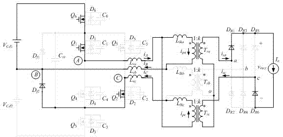
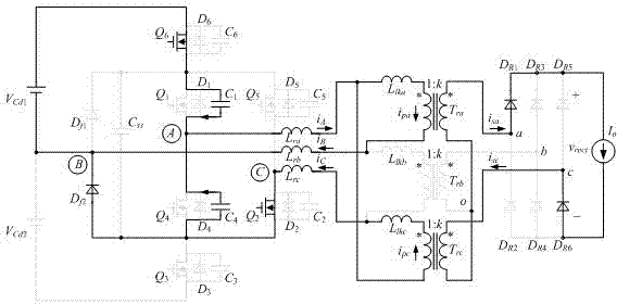
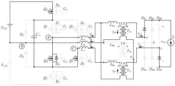
[0057] A specific embodiment of the present invention: input DC voltage: Vin=540~660V; output DC voltage: Vo=48V; output current: Io=20A; three-phase transformer primary side transformation ratio is 1:9; output filter inductance: Lf=22uH; MOSFET (Q1-Q6): IPW65R080CFD; freewheeling diode (Df1, Df2): DSEI30-06A; secondary rectifier diode (DR1-DR6): DSEP30-03A; switching frequency: fs=50kHz.

[0058] Figure 17~Figure 20 The driving voltages V of the switching tubes Q2 and Q5 when Vin is 540V and 660V and the output is fully loaded are given respectively. GS , drain-source voltage V DS and drain current I D At this time, the converter works in medium duty cycle mode and small duty cycle mode respectively. It can be seen from the figure that the voltage stress of all switching tubes is half of the input voltage. Before the switching tube is turned on, there is a reverse current in the drain, that is, the reverse parallel diode is turned on, and the voltage at both ends of the s...


PUM


Abstract

The invention discloses a method for asymmetrically controlling a simplified-type three-phase three-level direct-current converter. According to a control timing sequence, the conductive time of a first switching tube, the conductive time of a third switching tube and the conductive time of a fifth switching tube are the same, the variation range of the duty ratio is 0-1 / 2, the turn-on time of the first switch, the turn-on time of the third switching tube and the turn-on time of the fifth switching tube are separated by 1 / 3 switching period, and output voltages are controlled by adjusting the duty ratio of the first switching tube, the duty ratio of the third switching tube and the duty ratio of the fifth switching tube. The conductive time of a second switching tube, the conductive time of a fourth switching tube and the conductive time of a sixth switching tube are the same and are correspondingly and complementarily conductive with the fifth switching tube, the first switching tube and the third switching tube respectively, and the certain delay time is reserved between every two complementary switching tubes. According to the method, voltage stresses of all the switching tubes are all a half of input voltages, the current stresses and output filter inductances of the switching tubes can be reduced, the zero voltage switching of the switching tubes can be achieved, and the automatic equalization of input partial pressure capacitor voltages can be achieved.

Description

technical field [0001] The invention relates to an asymmetrical control method of a simplified three-phase three-level DC converter, belonging to the DC conversion field of power electronic conversion technology. Background technique [0002] The full-bridge converter has the advantages of simple circuit structure, constant frequency control, and soft switching of the switch tube, so it is widely used in medium and high-power DC conversion applications. As the output power of the converter increases, the current stress of the switching tube also increases. At this time, multiple converters or switching devices can be connected in parallel, but it will bring problems such as current sharing and complex control. To solve this problem, a three-phase full-bridge DC converter can be used, which adds a bridge arm to the full-bridge converter, and the transformer and rectifier bridge are all three-phase structures. The converter can effectively reduce the current stress of the swi...

Claims


Application Information

Patent Timeline
IPC IPC(8): H02M7/487H02M7/5387H02M1/14
Inventor 刘福鑫陈悦胡高平阮新波
Owner NANJING UNIV OF AERONAUTICS & ASTRONAUTICS
Why Eureka
Try Eureka