

Atomization ejection device and method for SNCR (Selective Non Catalytic Reduction) denitration
An injection device and denitrification technology, applied in the field of atomization injection device and circulating fluidized bed boiler, can solve the problems of reducing atomization quality, affecting denitration efficiency, reducing denitration efficiency, etc., and achieving obvious heating effect, uniform injection effect, and improved The effect of denitration efficiency
- Summary
- Abstract
- Description
- Claims
- Application Information
AI Technical Summary
Problems solved by technology
Method used
Image

Examples
Embodiment Construction
[0022]The present invention will be further described in detail below in conjunction with the accompanying drawings and examples. The following examples are explanations of the present invention and the present invention is not limited to the following examples.
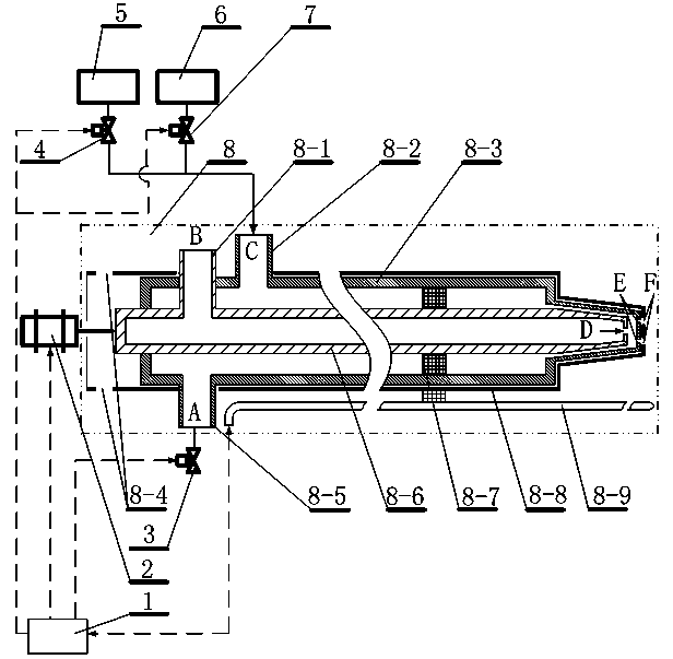
[0023] see figure 1 , a device for the atomization injection method of SNCR denitrification, including a PID control module 1, a motor 2, a drain valve 3, a solution valve 4, a liquid storage tank 5, a cooling water tank 6, a cooling water valve 7, and a spray gun 8.
[0024] The output end of the PID control module 1 is respectively connected with the input ends of the motor 2, the drain valve 3, the solution valve 4 and the cooling water valve 6, and the input end of the PID control module 1 is connected with the output ends of the temperature measuring devices 8-9.
[0025] The spray gun 8 includes an air intake pipe 8-1, a liquid inlet pipe 8-2, a solution pipe 8-3, a motor linkage hole 8-4, a liquid discharge pi...
PUM
 Abstract
Description
Claims
Application Information