
Process for cavitation repair welding of through-flow turbine set runner chamber

A runner chamber and cavitation technology, applied in the direction of turbines, mechanical equipment, manufacturing tools, etc., can solve the problems of inaccurate control, large thermal deformation of the runner chamber, damage, etc., to ensure welding quality, improve working strength and The effect of service life

Inactive Publication Date: 2014-01-15
SICHUAN SHUGANG HYDROPOWER ENG TECHCO
View PDF5 Cites 3 Cited by
  • Summary
  • Abstract
  • Description
  • Claims
  • Application Information

AI Technical Summary

Problems solved by technology

[0006] 1. When the cavitation part on the surface of the runner is melted by a high-current electric hammer, the high temperature generated by the high-current melting will affect a large range, and the high-temperature area is large, resulting in a large thermal deformation of the runner chamber
[0007] 2. In the blowing process of using electric 铇, because it cannot be precisely controlled, it is easy to cause more serious damage to the part that has not been subjected to cavitation, so that the welding amount becomes larger in the process of using electric welding, and the electric 铇 itself adopts high-current electric welding High temperature will be generated in the way, so that the workpiece to be welded will be deformed greatly
[0008] 3. Due to the thin wall of the runner chamber of the tubular unit, a high temperature is generated when the cavitation part on the surface of the runner is melted by a high-current electric hammer, and a high temperature is generated again when electric welding is used for repairing. Such multiple high-temperature processes make the The deformation of the runner chamber is more serious
[0009] 4. The surface of the runner is melted by high-current electric iron and the cavitation part after electric welding is repaired. Due to the large roughness and deformation of the welded surface, the amount of grinding in the correction and repair is very large, and the repair time is very long. , not only is it difficult to meet the satisfactory requirements, but also the economic loss caused

Method used


Image

  • Process for cavitation repair welding of through-flow turbine set runner chamber

Examples


Embodiment 1

[0032] The invention discloses a cavitation welding repair process for a runner chamber of a tubular unit, the steps of which are as follows:

[0033] A. Determine the cavitation location of the runner chamber;

[0034] B. Plan the shape of some cavitation parts that need to be polished according to the cavitation parts;

[0035] C. Grinding according to the planned shape, the depth of grinding is consistent with the depth of cavitation, forming a grinding groove;

[0036] D. Insert a stainless steel plate that matches the shape and depth of the planned grinding part into the grinding tank; the stainless steel plate is processed with multiple sieve holes that pass through the stainless steel plate;

[0037] E. Using the argon arc welding process, the welding repair is carried out from the screen hole in the middle of the stainless steel plate to the direction of both sides, and finally the joint between the stainless steel plate and the grinding groove is welded, and the stai...

Embodiment approach

[0039] The best implementation method of the present invention is as follows:

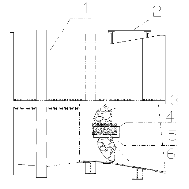
[0040] The accompanying drawings are described in detail as follows: 1 mentioned in the figure is the runner chamber of the tubular water turbine, which is located in the corridor of the hydropower station unit.

[0041] 2 in the figure is the inlet hole of the runner chamber of the tubular water turbine, which is the passage for the staff to enter the interior of the runner chamber after the flow channel of the unit has been drained.

[0042] 3 in the figure is the situation that the runner chamber of the tubular turbine is subjected to cavitation damage in different degrees during operation.

[0043] 4 in the figure is to analyze the situation of 3 in the figure, plan the scope of grinding according to the actual situation, and use a grinder to grind by hand within the grinding range, and polish the runner chamber according to the planned length, width and depth requirements. cavitation part.

...


PUM


Abstract

The invention discloses a process for cavitation repair welding of a through-flow turbine set runner chamber. The process is characterized by comprising a first step of determining a runner chamber cavitation part; a second step of planning the shape of part of the cavitation part needing polishing according to the cavitation part; a third step of performing polishing according to the planned shape, enabling the polishing depth to be consistent with the cavitation depth, and forming a polishing groove; a fourth step of enabling a stainless steel plate matched with the planned shape and the depth of the polished part to be embedded in the polishing groove, and enabling a plurality of sieve holes which cross through the stainless steel plate to be processed in the stainless steel plate; a fifth step of adopting an argon arc welding process, performing repair welding from the sieve holes in the middle of the stainless steel plate in the directions towards two sides, finally enabling the junction of the periphery of the stainless steel plate and the polishing groove to be welded, and enabling the polishing groove to be welded into the polishing groove. The process not only can guarantee that deformation of the runner chamber which is free of dismantling and lifting and undergoes repair welding is extremely small, but also enables the repaired runner chamber to completely meet safety in turbine set running, and the cavitation resistance of the runner chamber is improved to a large extent.

Description

[0001] technical field [0002] The invention relates to a welding repair process for the cavitation part of the runner chamber of the tubular unit. In the present invention, the runner chamber can be welded and repaired after the runner water is drained in the minor repair process without dismantling and lifting the runner chamber, and the runner chamber basically does not deform after the welding repair. Background technique [0003] The runner chamber of the water turbine is an important part that converts the water wheel into mechanical energy. During the process of water energy passing through the runner body and the runner chamber, some chemical and physical reactions occur on the runner blades and the inner wall of the runner. cavitation phenomenon. [0004] This kind of cavitation can directly damage the turbine runner blades and the runner chamber, and severe cavitation can easily cause the runner chamber to rupture. Structurally, the upper part of the runner ...

Claims


Application Information

Patent Timeline
Patent Type & Authority Applications(China)
IPC IPC(8): B23P6/00
CPCB23K9/02B23K9/235B23K2101/001
Inventor 仲德金
Owner SICHUAN SHUGANG HYDROPOWER ENG TECHCO
Learn More