Mechanical gripper with three-finger structure

A technology of mechanical grippers and grippers, applied in the field of manipulators, can solve problems such as long finger closing time, complex finger structure, and complex design structure, and achieve the effect of light weight, simple structure, and good stability

Inactive Publication Date: 2014-01-15
HARBIN INST OF TECH
View PDF6 Cites 15 Cited by
  • Summary
  • Abstract
  • Description
  • Claims
  • Application Information

AI Technical Summary

Problems solved by technology

[0004] The purpose of the present invention is to solve the problem of using connecting rod or mechanical transmission in the grasping transmission mode of the existing manipulator. The design structure of the connecting rod transmission is ...

Method used


Image

  • Mechanical gripper with three-finger structure
  • Mechanical gripper with three-finger structure
  • Mechanical gripper with three-finger structure

Examples


specific Embodiment approach 1

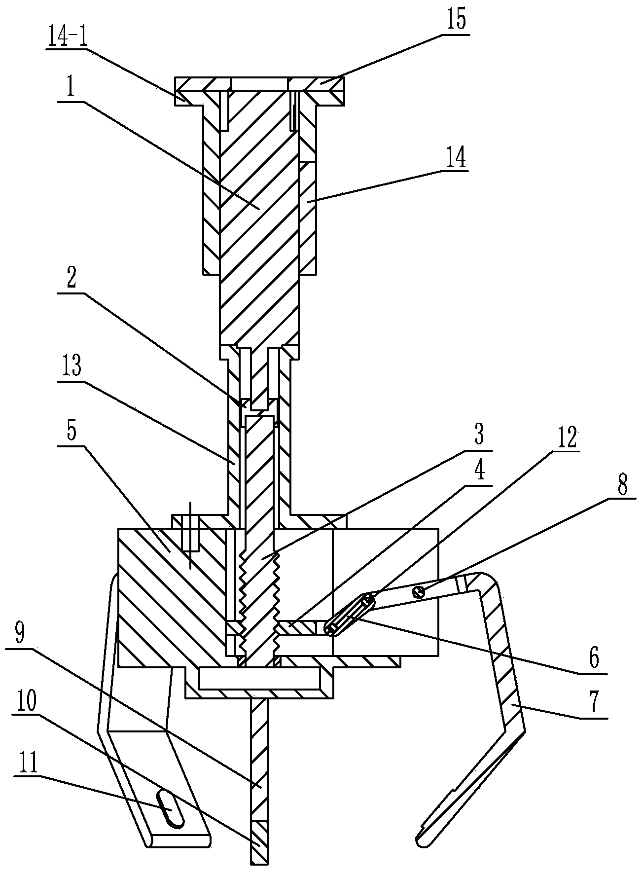
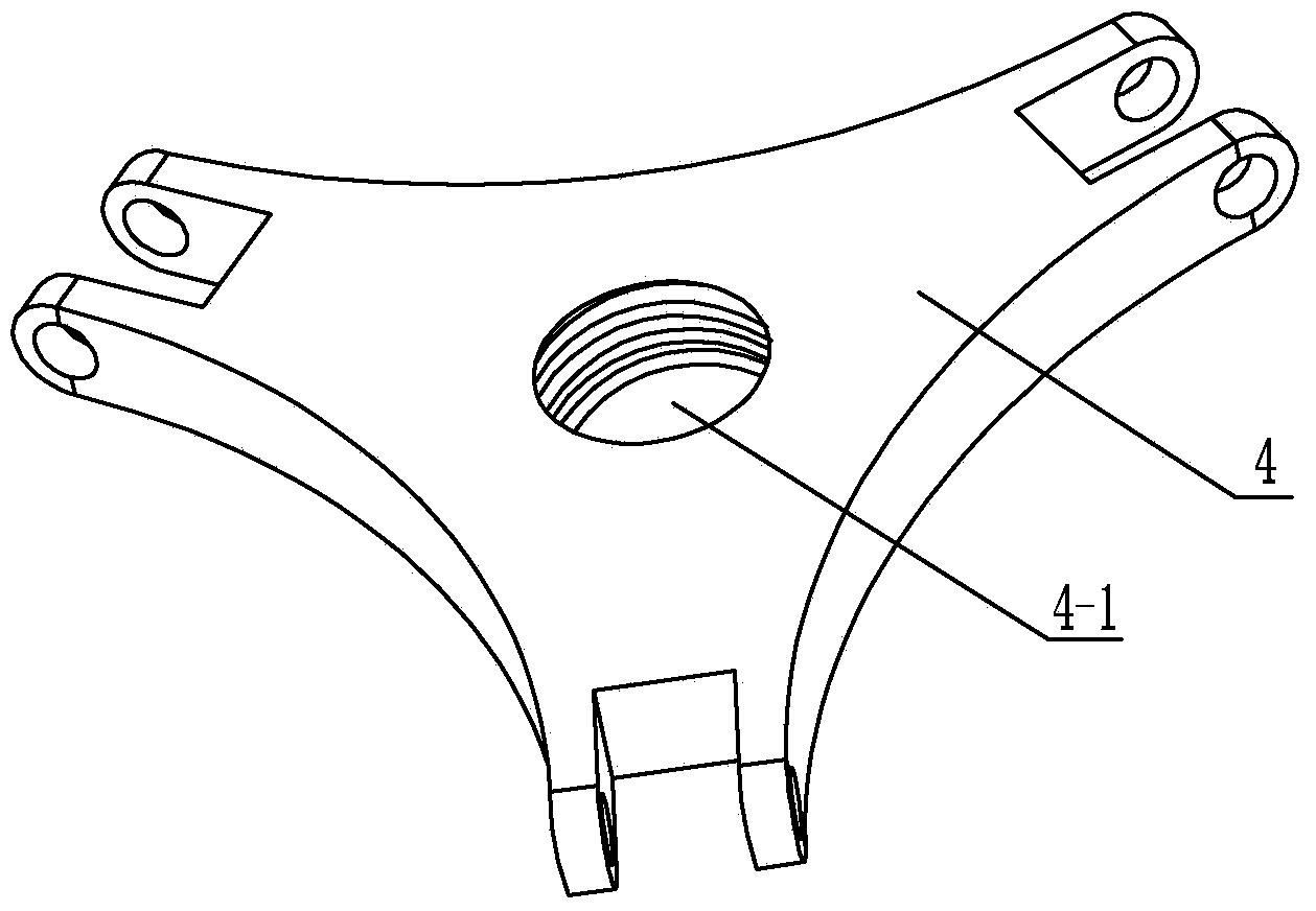
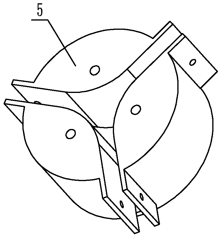
[0011] Specific implementation mode one: combine Figure 1 ~ Figure 4 Describe this embodiment. This embodiment includes a motor 1, a coupling 2, a screw 3, a slider 4, a claw housing 5, a probe 9, a signal sensor 10, three connecting rods 6, three fingers 7, Three fixed shafts 8 and three switch sensors 11, the output end of the motor 1 is connected with the screw rod 3 through the coupling 2, the center of the slider 4 is provided with a threaded hole 4-1, and the slider 4 is threaded with the screw rod 3, The slider 4 moves along the axial direction of the screw rod 3, and the three connecting rods 6 are evenly distributed along the same circumference. One end of each connecting rod 6 is connected to the slider 4 through a connecting shaft 12, and the other end of each connecting rod 6 is connected to The shaft 12 is connected with a finger 7, the finger 7 is installed on the gripper housing 5 through the fixed shaft 8, the finger 7 opens or closes around the fixed shaft 8,...

specific Embodiment approach 2

[0013] Specific implementation mode two: combination figure 1 Describe this embodiment, the difference between this embodiment and specific embodiment 1 is that it also adds a connecting sleeve 13, the connecting sleeve 13 is sleeved on the output shaft of the motor 1, the coupling 2 and the screw rod 3, and the connecting sleeve 13 The lower end of the lower end is fixedly connected with the claw housing 5 through a connecting element. This design makes the mechanical transmission complete in a closed environment, making the transmission more stable. Other components and connections are the same as those in the first embodiment.

specific Embodiment approach 3

[0014] Specific implementation mode three: combination figure 1 This embodiment is described. The difference between this embodiment and the specific embodiment 1 or 2 is that it also adds a motor fixing sleeve 14 , and the motor fixing sleeve 14 is sleeved on the motor 1 . The motor fixing sleeve 14 is used to fix the motor 1 . Other compositions and connections are the same as those in Embodiment 1 or Embodiment 2.


PUM


Abstract

The invention relates to a mechanical arm, in particular to a mechanical gripper with a three-finger structure. The mechanical gripper aims to solve the problems that connecting rod transmission or mechanical transmission is adopted in a grabbing transmission mode of an existing mechanical arm, the connecting rod transmission is complex in designed structure, the mechanical transmission is long in finger closing time, the structure of fingers is complex, and breakdowns can happen easily. An output end of a motor is connected with a screw through a coupler, a threaded hole is formed in the center of a slider, the slider is in threaded connection with the screw, three connecting rods are evenly arranged along the same circumference, one end of each connecting rod is connected with the slider, the other end of each connecting rod is connected with one finger, the fingers are arranged on a gripper shell through a fixed shaft, a switch sensor is arranged at the bottom of the central axis of each finger, probes are fixedly arranged on the lower end face of the gripper shell, and signal sensors are arranged at the lower ends of the probes. The mechanical gripper with the three-finger structure is used for grabbing cup-shaped targets by robots.

Description

technical field [0001] The invention relates to a manipulator, in particular to a manipulator claw with a three-finger structure. Background technique [0002] With the deepening of robot research and the huge growth of various demands, the application fields of robots are constantly expanding, and the concepts are also constantly expanding. They are no longer limited to industrial robots for handling, welding and mass operations. Humans have successfully developed or Special robots for dangerous environment operations, marine resource detection, nuclear energy utilization, military reconnaissance and space detection are being developed. Robots have been widely used in computer-controlled intelligent electromechanical device systems in various fields. While the robot has been greatly developed, the robot gripper, one of the key components of the robot, has also made great progress. [0003] At present, the transmission methods of the manipulator mainly include tendon trans...

Claims


Application Information

Patent Timeline
IPC IPC(8): B25J15/10B25J9/12
Inventor 葛连正梁培栋赵立军陈键王珂李瑞峰
Owner HARBIN INST OF TECH
Why Eureka
Try Eureka