Supercharge Your Innovation With Domain-Expert AI Agents!

Atomized water cooling device of sintered ore

A cooling device and atomized water technology are applied in the field of devices for cooling hot sintered ore with air and atomized water in metallurgical enterprises. , the device maintenance is small, the effect of saving electric energy

Inactive Publication Date: 2014-01-15
苏州科睿特能源科技有限公司
View PDF8 Cites 2 Cited by
  • Summary
  • Abstract
  • Description
  • Claims
  • Application Information

AI Technical Summary

Problems solved by technology

[0005] 1. Since the spray device is installed in the air duct, it is inconvenient to overhaul
[0006] 2. The pressure of the water is controlled at 0.05-0.4MPa. The pressure is obviously insufficient, and the water cannot be fully converted into atomized water, and a large amount of water will condense on the inner wall of the cooling air duct, wind box, etc., so the patent mentions The device includes the air duct drainage pipe, the main purpose of which is to discharge a large amount of water that has not been fully atomized and evaporated, resulting in a waste of water resources
[0007] 3. There is one nozzle installed at a certain position, or several nozzles are connected in parallel, so that when the hot sinter is cooled, the atomized water formed by the atomization nozzle is not evenly distributed in space, so that the cooling of the hot sinter is uneven. Uniform, adversely affects the cooling effect
[0008] 4. The distance between the nozzle and the spreading grate has not been determined, and the aperture of the nozzle has not been determined

Method used


Image

  • Atomized water cooling device of sintered ore
  • Atomized water cooling device of sintered ore
  • Atomized water cooling device of sintered ore

Examples


Embodiment Construction

[0030] The specific embodiments of the present invention will be described in further detail below in conjunction with the accompanying drawings.

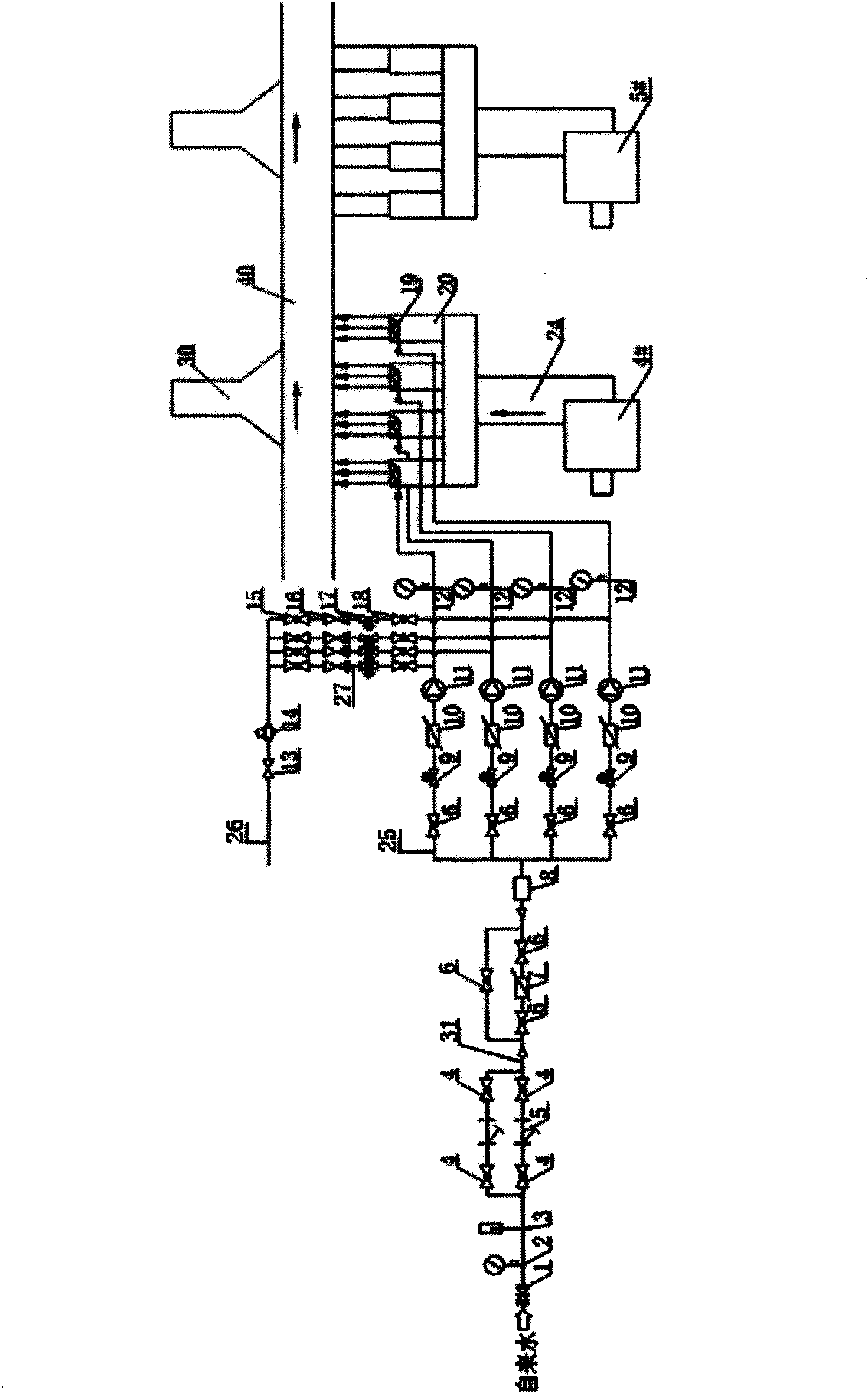
[0031] As shown in the figure: the cooling device of the sintering machine has five blowers placed in sequence. Because the first three can produce higher temperature flue gas, the waste heat is recycled through the flue gas waste heat boiler and the condensing steam turbine generator. There is no need to install an atomized water cooling device. After a sintered ore atomized water cooling device is installed on the fourth blower, the fifth blower can be stopped.

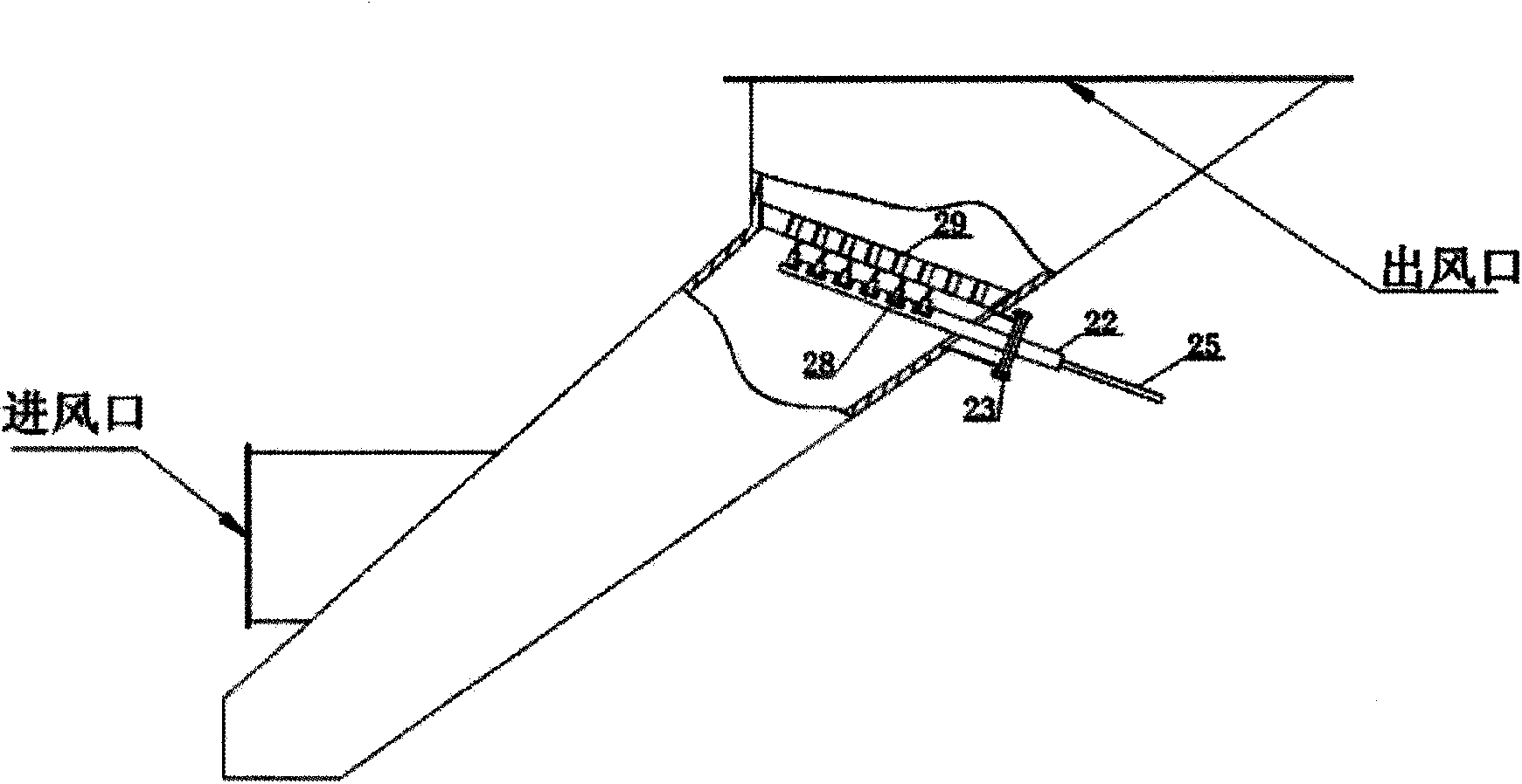
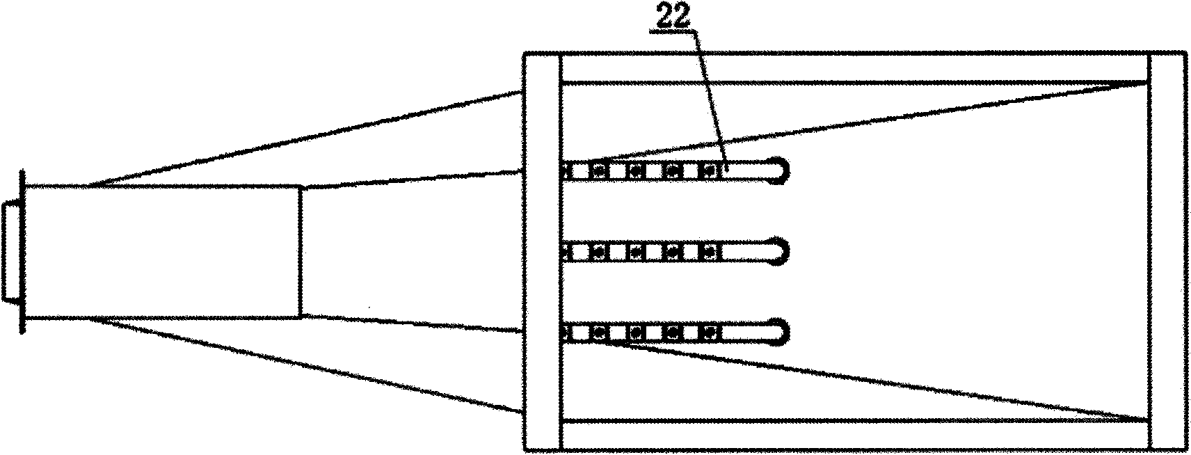
[0032] A cooling device for a sintering machine includes a grate plate 40, a blower, an air pipe 24, an air pipe branch 20, and a chimney 30. One end of the air pipe 24 is connected with the blower, and the other end of the air pipe 24 is provided with 4 air pipe branches 20 in parallel. The air duct branch 20 is located below the grate 40, the air outlet of the duct branch 2...


PUM


Abstract

The invention discloses an atomized water cooling device of sintered ore. A plurality of water pipe branches in parallel are connected with a water main; a gate valve, a filter device and a flow measurement device are sequentially mounted on the water main; a high pressure plunger pump, a pressure gauge and a spraying device are sequentially mounted on each water pipe branch; each spraying device consists of a plurality of headers in parallel; a plurality of tandem nozzles are mounted at one end of each header and positioned in air pipe branches; a distance between each nozzle and a laying grid plate is greater than 0.5m; the hole diameter of each nozzle is 0.05-0.3mm; the other ends of the headers penetrate through the air pipe branches, extend out of the air pipe branches and are connected with the water pipe branches; the headers are fixedly mounted on the air pipe branches by connecting devices; and the connecting devices allow the headers to be capable of being drawn out of the air pipe branches. According to the device, the cooling efficiency of a cooling blower can be effectively improved, the electric energy is greatly saved, the original device is not required to be subjected to structural change during transformation, the mounting is simple, and the device overhaul workload is low.

Description

Technical field [0001] The invention relates to a device for cooling raw materials, in particular to a device for cooling the hot sintered ore of metallurgical enterprises with air and atomized water. Background technique [0002] Sinter is one of the most important raw materials for blast furnace ironmaking in metallurgical enterprises. The sinter cooling process is to cool the hot sinter from 700 to 1000°C to below 150°C. The cold sinter is beneficial to the transportation of sinter and finished product processing and storage, and it can also improve the environmental working conditions of the production area. The use of cold sinter is meaningful to strengthen blast furnace smelting, increase blast furnace output, reduce coking, and extend the life of furnace top equipment. The sinter cooling process uses special cooling devices. There are two cooling methods: suction cooling and blast cooling. At present, blast cooling is generally used. Cooling devices include ring coolers ...

Claims


Application Information

Patent Timeline
Patent Type & Authority Applications(China)
IPC IPC(8): C22B1/26
Inventor 徐欣
Owner 苏州科睿特能源科技有限公司
Features
  • R&D
  • Intellectual Property
  • Life Sciences
  • Materials
  • Tech Scout
  • Unparalleled Data Quality
  • Higher Quality Content
  • 60% Fewer Hallucinations
Learn More