
Vacuum treatment system valve assembly and chemical vapor deposition system

A chemical vapor deposition, valve assembly technology, applied in gaseous chemical plating, metal material coating process, coating and other directions, can solve the problems of sealing between processing chamber and transmission chamber, difficult conduction control, complex sealing valve structure, etc. , to achieve strong corrosion resistance, improve sealing and conduction effects, and improve work stability.

Active Publication Date: 2014-01-15
理想万里晖真空装备(泰兴)有限公司
View PDF5 Cites 0 Cited by
  • Summary
  • Abstract
  • Description
  • Claims
  • Application Information

AI Technical Summary

Problems solved by technology

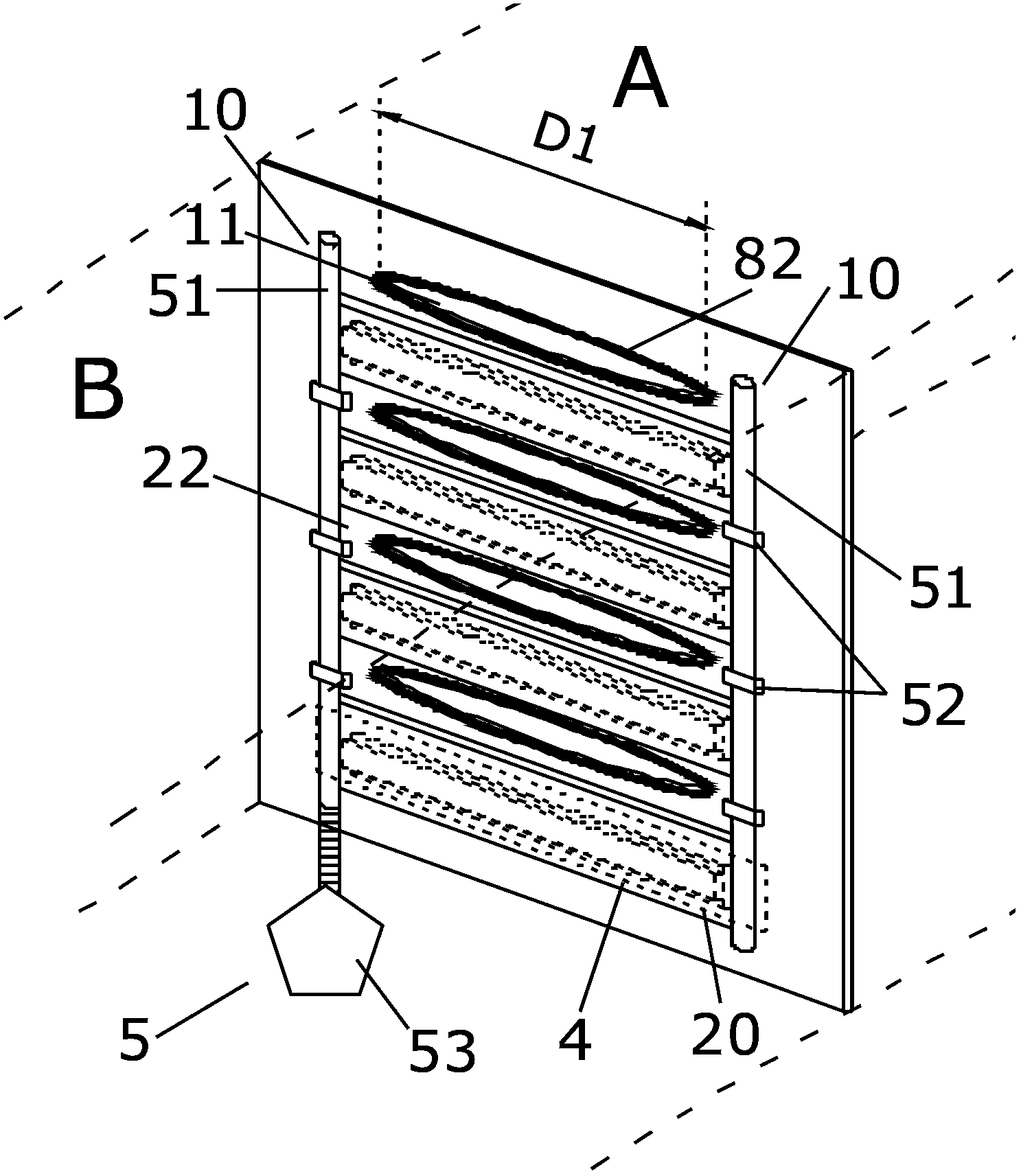
[0009] In view of the existing thin film deposition technology, the structure of the sealing valve between the processing chamber and the transmission chamber is complicated, the sealing and conduction process of the processing chamber and the transmission chamber are cumbersome, and thus the sealing between the processing chamber and the transmission chamber and the conduction control are difficult, etc. Defects, the present invention provides a vacuum processing system valve assembly and a chemical vapor deposition system, a sealing plate is set on the transmission through hole of the partition between the two isolation chambers, and the air bag is used to realize the gap between the sealing plate and the transmission through hole Opening and closing, so as to realize the conduction and sealing between the two isolated chambers

Method used


Image

  • Vacuum treatment system valve assembly and chemical vapor deposition system
  • Vacuum treatment system valve assembly and chemical vapor deposition system
  • Vacuum treatment system valve assembly and chemical vapor deposition system

Examples


Embodiment Construction

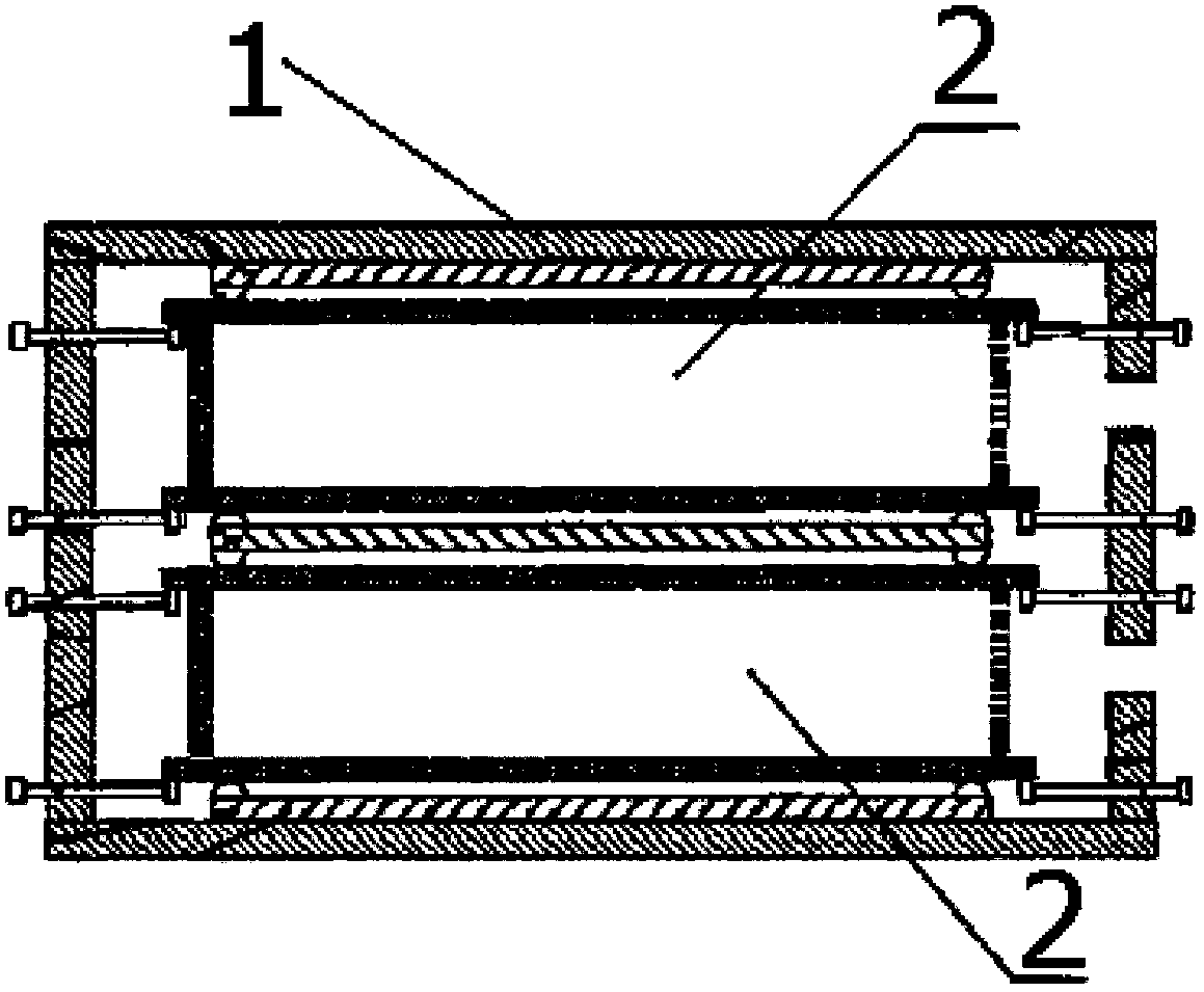
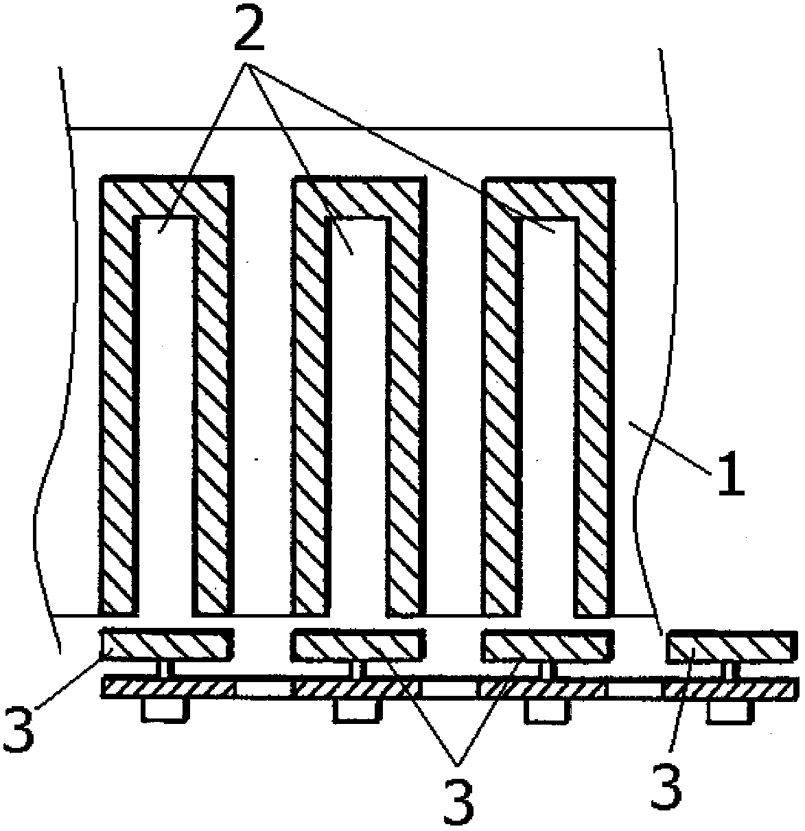
[0053] As described in the background art, in the PECVD process, in order to improve the production efficiency of PECVD film deposition, the PECVD processing chamber includes a plurality of reaction sub-chambers. However, as in the solar panel substrate film deposition process, the length of the opening between each reaction sub-chamber and the transfer chamber is large, and both sides of the sealing valve (between the transfer chamber and each reaction sub-chamber) during the PECVD film deposition process Due to the large pressure difference and the pressure difference between the reaction sub-chambers, it is difficult to ensure the tightness of each reaction sub-chamber 2 in the thin film deposition process by using a single sealing valve. Therefore, in the existing PECVD system, an independent sealing valve is generally arranged between each reaction sub-chamber and the transmission chamber, and the sealing or opening linkage control between the sealing valves is realized thr...


PUM

PropertyMeasurementUnit
surface areaaaaaaaaaaa

Abstract

The invention discloses a vacuum treatment system valve assembly and a chemical vapor deposition system. The vacuum treatment system valve assembly comprises a partition board provided with transmission through holes and sealing valve mechanisms corresponding to the transmission through holes; each sealing valve mechanism comprises a backboard, a sealing board arranged on the backboard, and an airbag which is located between the backboard and the partition board and is used for controlling sealing of the sealing board on each transmission through hole, and the sealing board is matched with a through hole structure; the airbag operating temperature is higher than 100 DEG C. The vacuum treatment system valve assembly controls opening and closing of the transmission through holes on the partition board and the sealing boards by the airbag so as to realize conduction and sealing of two sides of the partition board, and improves the sealing and conduction effects of the two sides of the partition board; and besides, the airbag work temperature is higher than 100 DEG C, so that the working stability of the vacuum treatment system valve assembly is improved, and even under a condition of high temperature, stability of a thin film deposition technological process is not affected.

Description

Technical field [0001] The invention relates to a vacuum isolation component, in particular to a valve component of a vacuum processing system and a chemical vapor deposition system. Background technique [0002] Solar photovoltaic power generation refers to a power generation technology that uses photovoltaic effect to convert light energy into electrical energy. The energy of sunlight is inexhaustible and inexhaustible. It is the most important energy source for achieving sustainable development. In particular, the second-generation thin-film solar cells have become a research hotspot in recent years due to a series of advantages such as low energy consumption and environmental protection. [0003] The structure of thin-film solar cells generally includes a substrate, a transparent electrode, a p-type doped silicon film, an i-layer (non-doped or intrinsic silicon film), an n-type doped silicon film, a back electrode, and a protective plate. Among them, the p-type doped silicon f...

Claims


Application Information

Patent Timeline
Patent Type & Authority Applications(China)
IPC IPC(8): C23C16/52C23C16/54
Inventor 胡兵吴红星
Owner 理想万里晖真空装备(泰兴)有限公司
Learn More