Heat management control system and method and device for controlling branch circulation loops
A circulation loop and control system technology, applied in the direction of measuring devices, instruments, machine/structural component testing, etc., can solve the problems of occupying a large laboratory area and high equipment cost
Active Publication Date: 2014-01-15
WEICHAI POWER CO LTD
5 Cites 4 Cited by
AI-Extracted Technical Summary
Problems solved by technology
[0003] The existing method of setting different thermal management control systems for different devices such as engines and motors needs to arrange multiple sets of thermal management control systems in one laboratory, and the setting of...
Method used
[0041] In addition, a voltage sensor and a current sensor can also be provided at the power supply of the voltage provided by the water pump to detect the power consumption of the water pump and realize the monitoring of the power cons...
Abstract
The invention provides a heat management control system and a method and device for controlling branch circulation loops. The heat management control system is applied to hybrid power assembly tests and comprises the device for controlling the branch circulation loops, a first water tank and a water pump, at least two branches are connected to a water outlet header pipe of the water pump, each branch is provided with a throttle valve and a heat-management-required device, and therefore one branch circulation loop is formed by the throttle valve on each branch, the heat-management-required device on the branch, the water pump on a master and the water tank on the master. In the heat management control system, the only one water pump can be allocated, the heat-management-required devices are connected to the branches of the water pump, and the multiple heat-management-required devices can be managed through the one heat management control system. Compared with the prior art, the integrated heat management control system has the advantage that the occupied area is saved. In addition, due to the fact that the heat management control system does not require multiple water pumps, the device cost is also saved.
Application Domain
Engine testing
Technology Topic
Hybrid powertrainThrottle +5
Image
Examples
- Experimental program(1)
Example Embodiment
[0035] In order to make the above objects, features and advantages of the present invention more obvious and understandable, the specific embodiments of the present invention will be described in detail below with reference to the accompanying drawings.
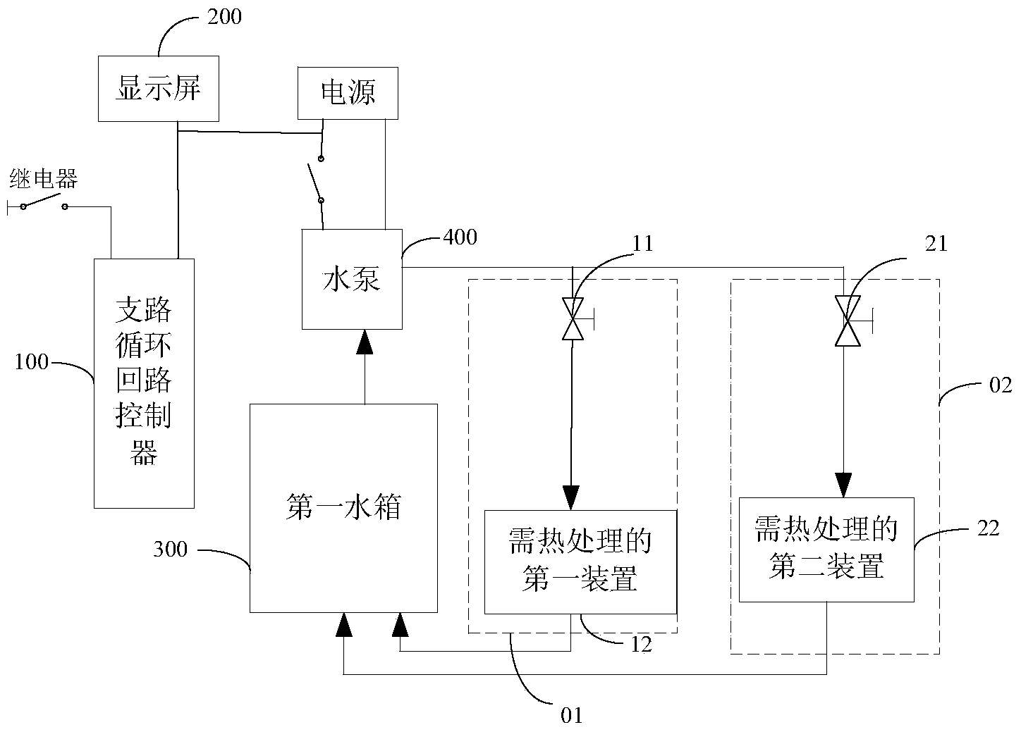
[0036] Such as figure 1 The thermal management control system shown is applied to the bench test of a hybrid powertrain. It includes a branch circuit loop controller 100, a display screen 200, a first water tank 300, a water pump 400, and a first water main pipe connected to the water pump 400. A branch road 01 and a second branch road 02, the first branch road 01 is provided with a first throttle valve 11 and a first device 12 requiring thermal management, and a second throttle valve is provided on the second branch road 02 21 and the second device 22 requiring thermal management. In order to form a water circulation circuit, the various components are connected by water pipes. The water pipe can be a hard pipe or a hose. Among them, the branch circulation loop controller 100 is used to control the opening degree of the throttle valve on each branch, so as to realize the control and management of the devices requiring thermal management.
[0037] The opening degrees of the first throttle valve 11 and the second throttle valve 21 can be adjusted according to the water flow requirements of the first device 12 requiring thermal management and the second device 22 requiring thermal management.
[0038] From figure 1 It can be seen that the inlet pipe of the water pump 400 is connected to the first water tank 300, and the first branch 01 connected to the outlet main pipe of the water pump 400 is connected to the inlet pipe of the first device 12 requiring thermal management through the first throttle valve 11. The outlet pipe of the first device 12 requiring heat management is connected to the first water tank 300, so that the first water tank 300, the water pump 400, the first throttle valve 11 and the first device 12 requiring heat treatment form a first branch circulation loop .
[0039] In addition, the second branch 02 connected to the outlet main pipe of the water pump 400 is connected to the inlet pipe of the second device 22 requiring thermal management through the second throttle valve 21, and the outlet pipe of the second device 22 requiring thermal management is connected to The first water tank 300 is connected. As a result, the first water tank 300, the water pump 400 and the components on the second branch form a second branch circulation loop. Specifically, the first water tank 300, the second water pump 400, the second throttle valve 21, and the second device 22 requiring thermal management constitute a second branch circulation circuit.
[0040] In addition, in order to achieve better control of the thermal management control system, temperature sensors and flow sensors are further installed at the water inlets of the various devices or components of the thermal management control system ( figure 1 Not shown in) to detect the water temperature and water flow of each water inlet pipe in real time, and furthermore, a temperature sensor can be set at the outlet of the water pipe to detect the water temperature of each water outlet pipe in real time.
[0041] In addition, a voltage sensor and a current sensor can be installed at the power supply of the water pump to detect the power consumption of the water pump and realize the monitoring of the power consumption of the water pump.
[0042] In the thermal management control system provided by this embodiment, since the first water tank 300 and the water pump 400 are located on the main circuit of the circulation circuit, they respectively form a branch circulation circuit with the throttle valve on the branch and the device requiring heat management. Such an integrated thermal management control system can independently perform thermal management on multiple branches at the same time. For example, when a device on a branch needs to be cooled, but the devices on other branches do not need to be cooled, open the throttle valve on the branch to allow water to flow through, so as to cool the device and close the nodes on other branches. The flow valve prevents water from flowing through the branch. Therefore, the thermal management control system provided by the embodiment of the present invention can realize independent control of multiple devices that require thermal management installed on different branches through only one water pump. Compared with the prior art method that needs to configure a thermal management control system for each device requiring thermal management, this thermal management control system can save the footprint of the thermal management system, and at the same time, the heat treatment system can only be installed A water pump, so to some extent, the heat treatment system reduces equipment costs.
[0043] In addition, in the prior art, when two devices need to be thermally managed, the two corresponding thermal management control systems need to be activated respectively. However, the heat treatment system provided in this embodiment only needs to be activated once, which simplifies the operation.
[0044] In addition, when the thermal management control system in the prior art fails, each cooling system needs to be checked, but this embodiment only has one thermal management control system, so the workload of maintenance personnel is reduced.
[0045] It should be noted that the existing hybrid power is generally oil and electricity, so the power source of the existing hybrid vehicle is generally an engine and a motor. Therefore, when doing a hybrid powertrain bench test, it is usually necessary to control the temperature of the engine and the motor to keep the temperature within the allowable range. For the engine, its temperature can neither be too high nor too low, so when the temperature is high, it needs to be cooled, and when the temperature is low, it needs to be heated. As for the motor, generally speaking, the lower the temperature, the better, and generally only cool it. Therefore, in this embodiment, it can be further defined that the first device requiring thermal management may be an engine, and the second device requiring thermal management may be an electric motor.
[0046] When the first device requiring thermal management is an engine, it can also be figure 2 As shown, a second water tank 13 is provided between the first throttle valve 11 and the first device 12 requiring thermal management, and a fourth throttle valve 14 is provided between the second water tank 13 and the first water tank 300 to A first sub-circulation circuit is formed between the first water tank 300, the water pump 400, the first throttle valve 11, the second water tank 13, and the fourth throttle valve 14. At the same time, a second sub-circulation loop is formed between the second water tank 13 and the engine 12'. In this case, the first branch circulation loop includes a first sub-circulation loop and a second sub-circulation loop. The second water tank 13 in the second sub-circulation loop is used to control the temperature of the engine 12' so that it is not higher than the first predetermined value. When the temperature of the engine 12' is too high, the first sub-circulation circuit is activated, so that the water in the first water tank 300 and the second water tank 13 can be circulated through the water pump 400, so that the water temperature of the second water tank can meet the cooling of the engine demand. In the thermal management control system provided by this embodiment, as long as the engine 12' is running, the second sub-circulation loop will run accordingly. And the operation of the second sub-circulation loop does not require power.
[0047] When the temperature of the engine is too low, such as lower than the second predetermined temperature, the engine needs to be heated. Therefore, in this embodiment, the thermal management control system also includes a heating device ( figure 2 Not shown in), used to heat the engine when the temperature of the engine is too low.
[0048] It should be noted that the thermal management control system provided by the present invention is not limited to only including two branches. If necessary, more branches can be provided on the thermal management control system, such as the third branch and the fourth branch. The branch,..., etc., and correspondingly, a throttle valve and a device requiring thermal management are provided on the branch.
[0049] In order to understand the inventive concept of the present invention more clearly, an embodiment of the present invention also provides a thermal management control system including three branches. For details, see image 3.
[0050] image 3 The thermal management control system shown has many similarities with the thermal management system of the first embodiment. For the sake of brevity, this embodiment only focuses on the differences between them. For the similarities, please refer to figure 1 description of.
[0051] See image 3 A third branch is also connected to the outlet header of the water pump of the thermal management control system, and a third throttle valve 31 and a third device 32 requiring thermal management are provided on the third branch 03. In practical applications, the third device 32 requiring thermal management may be a dynamometer. In order to clearly understand this embodiment, it can be considered that the arrangement on the third branch is the same as that on the second branch. Generally speaking, the first branch, the second branch, and the third branch are connected between the first water tank 300 and the water pump 400 as three parallel branches. Among them, the first water tank 300 and the water pump 400 are located on the main road.
[0052] From image 3 It can be seen that the third branch 03 connected to the outlet main pipe of the water pump 400 is connected to the inlet pipe of the third device 32 requiring thermal management through the third throttle valve 31. The third device 32 requiring thermal management The outlet pipe of is connected with the first water tank 300, so that the first water tank 300, the water pump 400 and the components on the third branch form a third branch circulation loop.
[0053] image 3 The thermal management control system shown is further integrated with the third branch, thus further improving figure 1 The described beneficial effects of the thermal management control system shown.
[0054] In order to realize the control of each branch circulation loop, the embodiment of the present invention provides a branch circulation loop control method. Combine Figure 4 , To describe in detail the flow of the control method. The branch circulation loop control method includes the following steps:
[0055] S41. Receive signals of the temperature of the inlet pipe, the temperature of the outlet pipe, and/or the initial flow rate of the inlet pipe carrying the device requiring thermal management:
[0056] Since temperature sensors are installed at the water inlet and outlet pipes of the devices requiring thermal management on each branch, the water temperature of the water inlet pipe and the water outlet pipe can be detected respectively. At the same time, a flow sensor is installed at the inlet pipe to detect the flow of water at the inlet pipe. The branch circulation loop controller receives the signals sent by the inlet pipe temperature sensor, the outlet pipe temperature sensor and/or the initial flow sensor of the inlet pipe. The signal carries information about the temperature of the inlet pipe, the temperature of the outlet pipe, and/or the initial flow rate of the inlet pipe of the device requiring thermal management.
[0057] S42. Obtain the required flow rate of the water inlet pipe of the device requiring heat management according to the signal of the temperature of the inlet pipe, the temperature of the outlet pipe and/or the initial flow rate of the inlet pipe carrying the device requiring heat management.
[0058] The demand flow rate is the flow rate required to cool the device requiring thermal management. The demand flow rate can make the temperature of the device requiring cooling reach a suitable temperature in a short time.
[0059] S43: Send an instruction carrying the demand flow rate of the water inlet pipe of the device requiring thermal management to the throttle valve on the branch corresponding to the device.
[0060] S44. Control the opening degree of the throttle valve on the branch according to the required flow rate of the water inlet pipe of the device requiring heat management.
[0061] Specifically, for each branch, the detected water temperature of the water inlet pipe and the water outlet pipe is the water temperature of the water inlet pipe and the water outlet pipe of the corresponding device requiring heat management on the branch, and the flow rate of the water inlet pipe is the corresponding demand on the branch. The flow rate of the inlet pipe of the thermal management device. For example, when controlling the first branch circulation loop on the first branch, the control method includes the following steps:
[0062] S411. Receive a signal carrying the temperature of the inlet pipe, the temperature of the outlet pipe, and/or the initial flow rate of the inlet pipe of the first device requiring thermal management;
[0063] S421. Obtain the required flow rate of the inlet pipe of the first device requiring heat management according to the signal of the inlet pipe temperature, outlet pipe temperature and/or initial flow rate of the inlet pipe of the first device requiring heat management ;
[0064] S431. Send an instruction carrying the demand flow rate of the water inlet pipe of the first device requiring thermal management to the first throttle valve;
[0065] S441. Control the opening degree of the first throttle valve according to the required flow rate of the water inlet pipe of the first device requiring heat management;
[0066] Based on a method similar to the control of the first branch circulation loop on the first branch, the second branch circulation loop on the second branch and the third branch circulation loop on the third branch are controlled, so as to control the circulation loop of each branch. Thermal management is performed on devices that require thermal management.
[0067] It should be noted that when the device requiring heat management on the branch is running, the circulation loop on the branch must be started, that is, the water pump 400 and the corresponding throttle valve on the branch must be opened. When the device requiring heat management on the branch stops, the circulation loop on the branch also stops.
[0068] In the branch circulation loop control method provided in this embodiment, since the water pump is located on the main pipe, the water pump can be started once, and the devices requiring thermal management on each branch can be controlled, so the control method is relatively simple and the operation is relatively easy.
[0069] As mentioned above, when the first device 12 requiring heat management on the first branch 01 is the engine 12', the first branch circulation loop includes a first sub-circulation loop and a second sub-circulation loop. When the engine is thermally managed, the first sub-circulation loop and the second sub-circulation loop need to be controlled. Since the operation of the second sub-circulation loop runs with the operation of the engine, it does not require external power, so there is no need to control the second sub-circulation loop. When the temperature of the engine is higher than the first predetermined temperature, the engine 12' is acquired according to the received signal of the temperature of the inlet pipe, the temperature of the outlet pipe, and/or the initial flow rate of the inlet pipe of the first device 12 that requires thermal management. The demand flow rate of the inlet pipe is then sent to the first throttle valve 11 and the fourth throttle valve 14 to control the opening of the first throttle valve 11 and the fourth throttle valve 14 to control the first throttle valve 11 and the fourth throttle valve 14 The water temperature of the second water tank 13 meets the requirement of engine cooling.
[0070] Based on the foregoing branch circulation loop control method, an embodiment of the present invention also provides a branch circulation loop control device. The branch circulation loop control device is applied to a heat management system for hybrid powertrain bench testing. See Figure 5 , The branch circulation loop control device includes,
[0071] The receiving unit 51 is configured to receive signals of the temperature of the inlet pipe, the temperature of the outlet pipe, and/or the initial flow rate of the inlet pipe carrying the device requiring thermal management on the branch;
[0072] The acquiring unit 52 is configured to acquire the water inlet pipe of the heat management device according to the signal of the inlet pipe temperature, the outlet pipe temperature and/or the initial flow rate of the inlet pipe of the heat management device on the branch Demand flow;
[0073] The sending unit 53 is configured to send an instruction carrying the demand flow rate of the water inlet pipe of the device requiring heat management to the throttle valve on the branch corresponding to the device;
[0074] The control unit 54 is configured to control the opening degree of the throttle valve on the branch according to the required flow rate of the water inlet pipe of the device requiring heat management.
[0075] It should be noted that, in the embodiment of the thermal management control system of the present invention, the role and function of the branch circulation loop controller 100 are the same as the above-mentioned branch circulation loop control device. It can also be understood that the branch circulation loop The loop controller 100 is a branch loop loop control device.
[0076] The above are only preferred embodiments of the present invention, and do not limit the present invention in any form. Although the present invention is disclosed as above in preferred embodiments, it is not intended to limit the present invention. Anyone familiar with the art, without departing from the scope of the technical solution of the present invention, can use the methods and technical content disclosed above to make many possible changes and modifications to the technical solution of the present invention, or modify it into equivalent changes. Examples. Therefore, any simple modifications, equivalent changes and modifications made to the above embodiments based on the technical essence of the present invention without departing from the technical solutions of the present invention still fall within the protection scope of the technical solutions of the present invention.
PUM


Description & Claims & Application Information
We can also present the details of the Description, Claims and Application information to help users get a comprehensive understanding of the technical details of the patent, such as background art, summary of invention, brief description of drawings, description of embodiments, and other original content. On the other hand, users can also determine the specific scope of protection of the technology through the list of claims; as well as understand the changes in the life cycle of the technology with the presentation of the patent timeline. Login to view more.