Broadband coherent polar region deep-layer ice penetrating radar system

An ice-penetrating radar and deep-layer technology, applied in the field of radar, can solve the problems of small average energy, limited application, and limitations, and achieve the effect of increasing average power, increasing dynamic range, and increasing processing income

Inactive Publication Date: 2014-01-15
INST OF ELECTRONICS CHINESE ACAD OF SCI
View PDF5 Cites 8 Cited by
  • Summary
  • Abstract
  • Description
  • Claims
  • Application Information

AI Technical Summary

Problems solved by technology

[0005] The technical disadvantages of traditional ice-penetrating radar include: (1) The transmission pulse is the Impulse system, and the average energy is small; (2) The antenna and the ground must be well coupled to ensure that the maximum energy can be transmitted underground; (3) The Impulse system radar system Generally, the equivalent sampling technology is adopted, and the speed of the moving platform is not required to be too high, which also limits the application of the radar on the fast moving platform
[0006] The above-mentioned characteristics of traditional ice-penetrating radar limit its application in polar deep ice detection, and also limit its application in vehicle and airborne platforms

Method used


Image

  • Broadband coherent polar region deep-layer ice penetrating radar system
  • Broadband coherent polar region deep-layer ice penetrating radar system
  • Broadband coherent polar region deep-layer ice penetrating radar system

Examples


Embodiment Construction

[0026] In order to make the object, technical solution and advantages of the present invention clearer, the present invention will be described in further detail below in conjunction with specific embodiments and with reference to the accompanying drawings.

[0027] The broadband coherent polar deep-layer ice-penetrating radar system of the invention can be used for detecting the deep-layer thickness of polar ice caps.

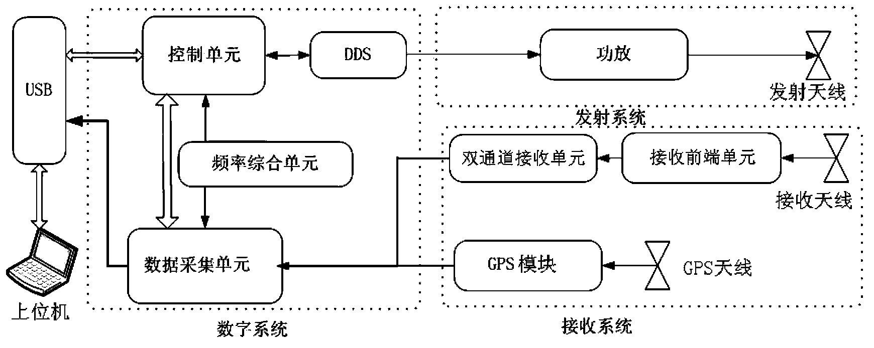
[0028] figure 1 It is a block diagram of the broadband coherent polar deep ice-penetrating radar system of the present invention. refer to figure 1 , the radar system includes a digital system, a receiving system and a transmitting system, as well as a USB interface and a host computer.

[0029] The digital system further includes: a control unit, a frequency synthesis unit, a data acquisition unit and a direct digital signal generator (DDS). The control unit is connected with the frequency integration unit, the data acquisition unit, and the DDS, and is co...


PUM


Abstract

The invention discloses a broadband coherent polar region deep-layer ice penetrating radar system which comprises a digital system, a receiving system and a transmitting system. The digital system comprises a control unit, a frequency synthesis unit, a data collecting unit and a DDS, wherein the control unit is used for controlling al the units of the radar system, the frequency synthesis unit is used for generating clock signals needed by the operation of the control unit and the data collecting unit, the data collecting unit is used for collecting analog signals and storing and transmitting GPS signals, and the DDS is used for generating linear frequency modulation signals sources. The transmitting system comprises a power amplifier and a transmitting antenna, wherein the power amplifier is used for carrying out power amplification on the linear frequency modulation signal sources generated by the DDS, and the transmitting antenna is used for radiating electromagnetic wave signals output by the power amplifier out. The receiving system comprises a double-channel receiving unit used for carrying out high-gain channel and low-grain channel amplification on the received signals output by the front end units. A wave band between VHF and UHF is selected as system working frequency, a frequency modulation pulse compression system is adopted, and the requirements for penetrability and the resolution ratio can be met.

Description

technical field [0001] The invention belongs to the technical field of radar, and in particular relates to a broadband coherent polar deep ice detection radar system, in which, according to the principle that ice has little attenuation of electromagnetic waves, electromagnetic waves are used to detect subglacial layers, and are used to detect the thickness of polar ice sheets and subglacial layered structure. Background technique [0002] The first method of using radar to detect polar glaciers was British Waite in the 1950s, and radar systems for this purpose developed rapidly thereafter. Traditional radar systems have adopted the short pulse system. [0003] In 1984, my country sent a team for the first time to conduct scientific expeditions to Antarctica. In the early 1980s, the Institute of Environment and Engineering for Cold and Arid Regions of the Chinese Academy of Sciences developed the B-1 thickness-measuring radar, and successfully tested it on the No. 1 Tiansha...

Claims


Application Information

Patent Timeline
IPC IPC(8): G01S7/489G01S17/88
CPCG01S7/282G01S7/288G01S7/34G01S13/26G01S13/885
Inventor 刘小军赵博方广有
Owner INST OF ELECTRONICS CHINESE ACAD OF SCI
Why Eureka
Try Eureka