RF system group delay parameter measuring method

A technology of radio frequency system and measurement method, applied in transmission system, relay system monitoring, transmission monitoring, etc., can solve problems such as difficult to accurately reflect curve fluctuation, complex structure of measuring device, low measurement accuracy, etc., and achieve adjustable measurement time, The effect of simplifying the measurement process and improving the measurement accuracy

Inactive Publication Date: 2014-01-15
BEIJING INST OF RADIO METROLOGY & MEASUREMENT
View PDF2 Cites 2 Cited by
  • Summary
  • Abstract
  • Description
  • Claims
  • Application Information

AI Technical Summary

Problems solved by technology

Among them, the sinusoidal modulation phase detection method obtains the time delay between the modulation information and the original information through phase detection, so the sinusoidal modulation phase detection method is susceptible to the influence of multipath reflection in the radio frequency system to be tested, and its measurement accuracy is low; pulse modulation peak value comparison The method determines the delay by peak detection first, and then compares the peak value of the modulated pulse. Therefore, there is a contradiction between the measurement accuracy of the pulse modulation peak comparison method and the measurement aperture, and it is difficult to accurately reflect the curve fluctuation of the group delay parameter of the RF system to be measured. ; The structure of the measuring device used by the BPSK receiver method is complex, cannot be calibrated, and it is difficult to improve the measurement accuracy through post-processing

Method used


Image

  • RF system group delay parameter measuring method

Examples


Embodiment 1

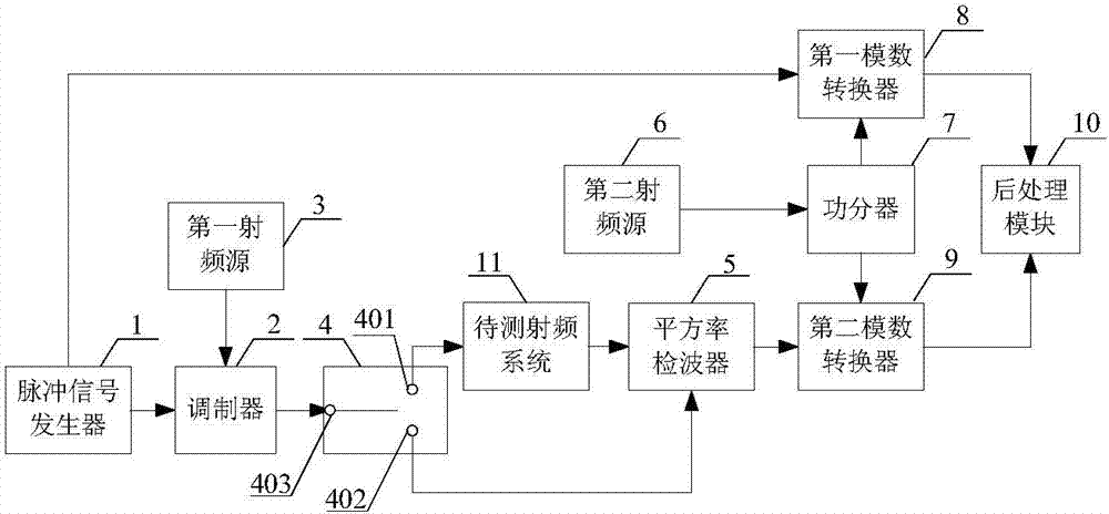
[0034] Such as figure 1 As shown, the measurement device used in the method for measuring the group delay parameter of the radio frequency system provided by this embodiment includes a pulse signal generator 1, a modulator 2, a first radio frequency source 3, a single pole double throw switch 4, a square rate detector 5, A second radio frequency source 6 , a power divider 7 , a first analog-to-digital converter 8 , a second analog-to-digital converter 9 and a post-processing module 10 . The SPDT switch 4 includes a first fixed terminal 401 , a second fixed terminal 402 and a moving contact 403 .

[0035] Two output terminals of the pulse signal generator 1 are electrically connected to an input terminal of the modulator 2 and an input terminal of the first analog-to-digital converter 8 respectively. The output end of the first radio frequency source 3 is electrically connected to the other input end of the modulator 2 . The output end of the modulator 2 is electrically conne...

Embodiment 2

[0054] The device for measuring the group delay parameter of the radio frequency system provided in this embodiment is the same as that in Embodiment 1.

[0055] The method for measuring the group delay parameter of the radio frequency system provided in this embodiment includes the following steps:

[0056] S1: close the moving contact of the SPDT switch 4 to the second fixed terminal 402, so that a signal path is formed between the modulator 2 and the square rate detector 5;

[0057] S2: Send the third pulse signal to the first analog-to-digital converter 8 through the pulse signal generator 1, and send the fourth pulse signal to the modulator 2 through the pulse signal generator 1, and both the third pulse signal and the fourth pulse signal are consistent with The first pulse signal is the same; there is a fixed second original time delay between the fourth pulse signal and the third pulse signal, and the second original time delay is the same as the first original time del...


PUM


Abstract

The invention discloses an RF system group delay parameter measuring method which comprises the steps as follows: the moving contact of a single-pole double-throw switch is combined with a first fixed terminal; a first pulse signal is sent to a first analog-digital converter through a pulse signal generator, and a second pulse signal is sent to a modulator through the pulse signal generator; a first carrier signal is sent to the modulator through a first RF source; the second pulse signal is modulated into the first carrier signal through the modulator; a signal with a new time delay is demodulated through a square law detector; a first synchronous sampling clock signal is sent to a power divider through a second RF source, and the first synchronous sampling clock signal from the second RF source is divided into two paths through the power divider. The measuring method utilizes the square law detector to demodulate a modulated signal, so as to avoid the introducing errors and improve the measuring accuracy which is better than 1 ns. The applicable frequency range of the measuring method is 100 MHz-50 GHz.

Description

technical field [0001] The invention relates to the technical field of measuring radio frequency system group time delay parameters, in particular to a method for measuring radio frequency system group time delay parameters. Background technique [0002] Group delay is a physical quantity used to describe the phase-frequency characteristics of a signal transmission system, and is one of the important performance indicators of a transmission system. Due to the limitation of the physical characteristics of the radio frequency system itself, there is inevitably phase dispersion in the radio frequency system, and the phase dispersion causes changes in group delay parameters at different frequency points, thus affecting signals transmitted in the radio frequency system. Therefore, it is of great significance to accurately measure the group delay parameters of the radio frequency system at different frequency points to determine the performance index of the entire radio frequency ...

Claims


Application Information

Patent Timeline
Patent Type & Authority Applications(China)
IPC IPC(8): H04B17/00H04B17/40
Inventor 陆晨曦李宏宇李闯年丰冯克明
Owner BEIJING INST OF RADIO METROLOGY & MEASUREMENT
Why Eureka
Try Eureka