

Method of fabricating an inertial sensor
A technology of inertial sensor and manufacturing method, which is applied in the field of inertial sensor, can solve the problems of deformation affecting the performance of strain gauge, difficulty in controlling small thickness polysilicon layer, and influence of tension, etc., and achieve the effect of good sensitivity
- Summary
- Abstract
- Description
- Claims
- Application Information
AI Technical Summary
Problems solved by technology
Method used
Image


Examples
Embodiment Construction
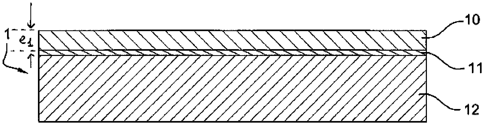
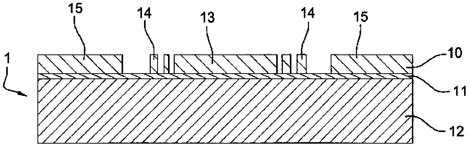
[0036] See attached Figure 15 , according to an embodiment of the invention, a piezoresistive or resonant inertial sensor, in particular, includes a piezoresistive or resonant measuring beam 23 and an active body composed of a movable standard mass 13 and a deformable plate 14 . The standard mass 13 is suspended in a closed cavity 30, 40, and the measuring beam 23 is connected with the deformable plate at the inner wall of the cavity. In particular, the thickness of the measuring beam 23 is smaller than that of the proof mass 13. Thus, for a resonant measuring beam 23, deflection of the proof mass 13 produces a change in the frequency of the resonator. In the case of a piezoresistive strain gauge measuring arm 23, the deflection of the proof mass 13 causes a change in the resistance of the strain gauge which can be recovered by means of the electrical contacts in the recess.
[0037] The method of fabricating such a sensor will be described below based on Figures 1 to 15 t...
PUM
 Abstract
Description
Claims
Application Information