
Differential scan imaging systems and methods

Active Publication Date: 2012-10-11
LI COR
View PDF10 Cites 7 Cited by
  • Summary
  • Abstract
  • Description
  • Claims
  • Application Information

AI Technical Summary

Benefits of technology

[0006]The present invention provides systems and methods for reducing or eliminating background related noise in optical imaging signals, and particularly to systems and methods for producing background-reduced fluorescence imaging signals.
[0008]Various embodiments offer simple, but efficient methods for obtaining a good estimate of the total background portion of a detected signal and removing the background to obtain an improved, background-reduced signal with better sensitivity due to the removal of all or a portion of the background signal.

Problems solved by technology

However, with all the techniques known to date, it is often difficult to completely prevent reflected and / or scattered excitation light from reaching the sensor.
This adds an amount of non-fluorescence signal to the emission signal which, in turn, results in a non-accurate measurement of target properties such as quantity of fluorescence material.
This is one type of optical background noise.
Yet another source of optical background noise is light generated by sources other than the excitation light sources that makes its way towards the sensor.
They, too, cause an increase in the background noise and if not eliminated or reduced, limit the performance of the imaging system.
And, as is well known in the optical imaging industry, techniques that work best for one type of background noise may not work well for others.

Method used


Image

  • Differential scan imaging systems and methods
  • Differential scan imaging systems and methods
  • Differential scan imaging systems and methods

Examples


Embodiment Construction

[0021]The present invention provides systems and methods for reducing or eliminating background-related noise in optical imaging signals, and particularly fluorescence imaging signals.

Differential Scanning with Coaxial Illumination

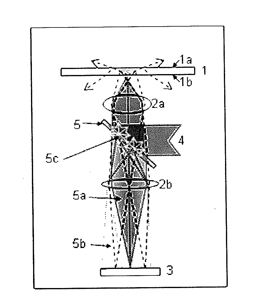
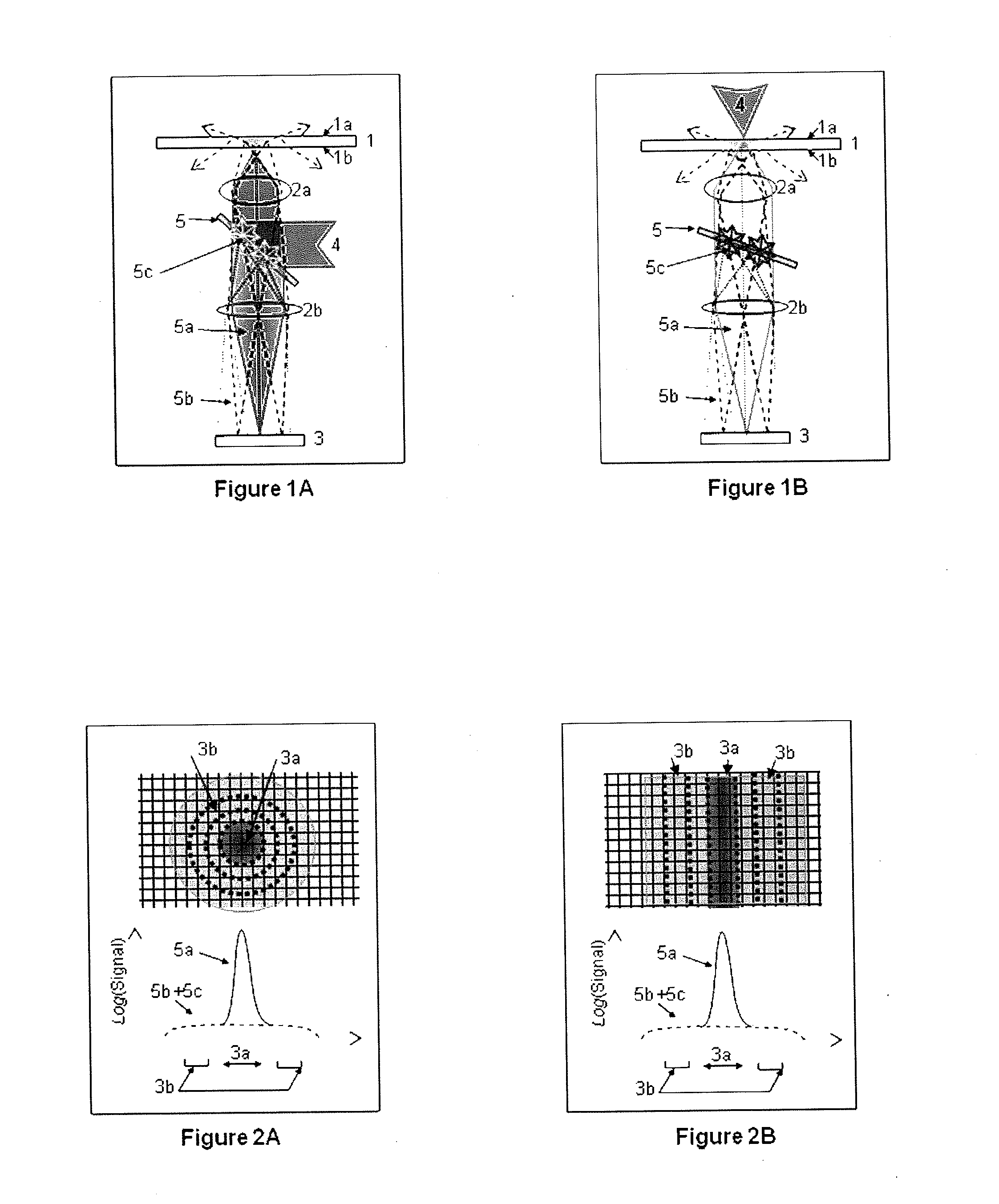
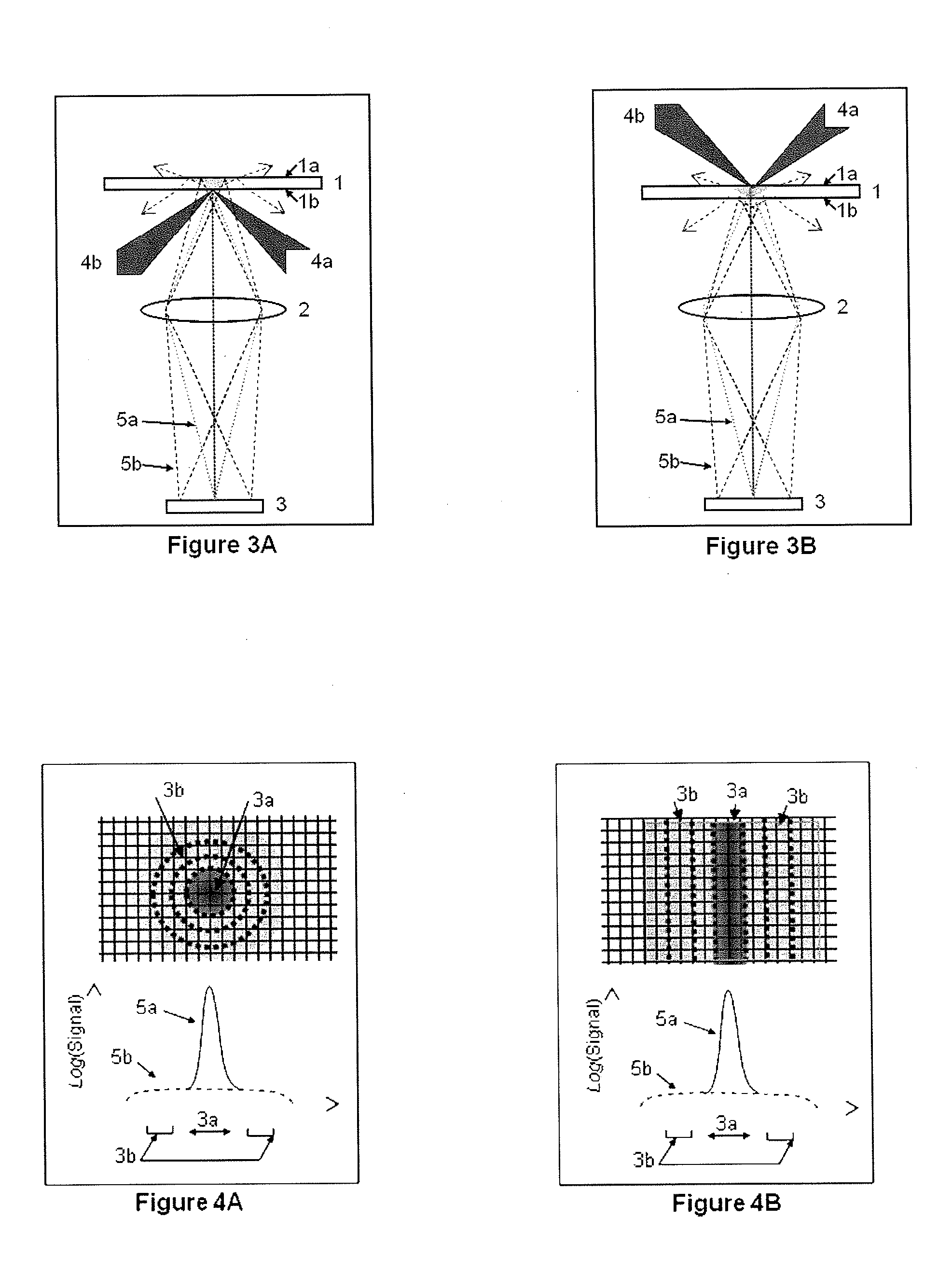
[0022]One type of fluorescence scanning system configuration is depicted by FIG. 1A. One or more fluorescently labeled targets are mounted on a platform 1 such as a glass plate, membrane coated slide, or other transparent, semi-transparent, and / or opaque media. A target area on the platform is illuminated by excitation light 4 which can be generated from laser source(s), LEDs, or broadband lamps and collected with some optical elements. The illumination light is typically filtered out using optical filters, dispersive elements, and the like to restrict the spectral content that arrives at the target plane, for example to excite only one of more than one fluorescence labels in the target plane. The fluorescence labels absorb a portion of the excitation ligh...


PUM


Abstract

Systems and methods for producing background-reduced fluorescence imaging signals include an illumination system that provides illumination light from an illumination source to a targeted area on the sample platform, a sensor adapted to detect light and having an array of sensing locations, and collection optics arranged and configured to project light emanating from the sample platform onto the sensor. In typical operation, light from the targeted area is projected onto a first portion of the sensor comprising a first plurality of the sensing locations and light from proximal to the targeted area on the platform is projected onto a second portion of the sensor comprising a second plurality of the sensing locations, and a second signal detected by the second portion of the sensor is subtracted from a first signal detected by the first portion of the sensor to produce a background-reduced signal, e.g., a signal with reduced background related noise.

Description

BACKGROUND[0001]The present invention relates to optical imaging with reduced background, and more specifically to systems and methods for directly measuring the amount of background noise and removing it from the detected signal.[0002]Optical imaging is becoming more and more the method of choice for many measurement applications that demand high sensitivity and quantification. Recent scientific advances benefit from reliably detecting small and / or weak targets. In order to obtain reliable representations of such targets, it is desirable to use an imaging system that has low noise levels. Fluorescence imaging is one of the techniques that have significant capabilities to reliably achieve sensitive, quantitative measurements. With fluorescence imaging, the target to be imaged is illuminated by an optical signal having a first spectral content (excitation light), and a portion of such a signal is absorbed by at least part of the target and is re-emitted as an optical signal of a seco...

Claims


Application Information

Patent Timeline
IPC IPC(8): H04N5/217
CPCG01N21/6456G01N2021/1785G02B21/16
Inventor BOUZID, AHMED
Owner LI COR
Learn More