A friction stir welding tool for lap joints

A technology of friction stir welding and lap joints, which is used in manufacturing tools, welding equipment, non-electric welding equipment and other directions. The effect of reducing the size of the defect and reducing the tendency of vertical migration

Inactive Publication Date: 2015-11-25
TIANJIN UNIV
View PDF6 Cites 1 Cited by
  • Summary
  • Abstract
  • Description
  • Claims
  • Application Information

AI Technical Summary

Problems solved by technology

When these common tools are used to weld lap joints, serious hook-shaped defects will occur in the weld, resulting in very low joint strength (the strength coefficient is mostly below 30%), and the hook-shaped defects cannot be alleviated only by optimizing the test process parameters

Method used


Image

  • A friction stir welding tool for lap joints
  • A friction stir welding tool for lap joints
  • A friction stir welding tool for lap joints

Examples


Embodiment

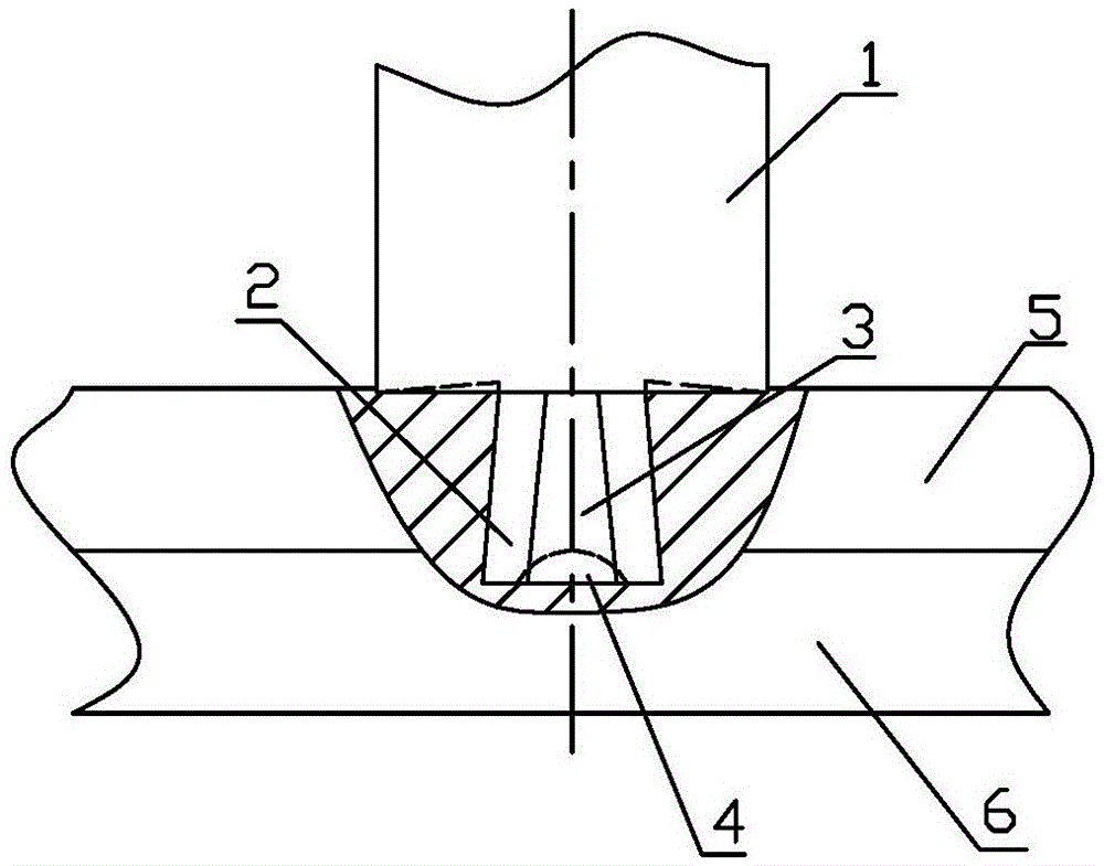
[0021] An aerospace structural part needs to involve lap joints of 5mm thick 2024 and 7075 dissimilar aluminum alloy plates. When welding the joints with ordinary cylindrical or conical threaded friction stir welding tools in the prior art, there are serious hooks in the joints. defect. Now according to the technical scheme provided by the present invention, a stirring tool suitable for this lap joint is processed.

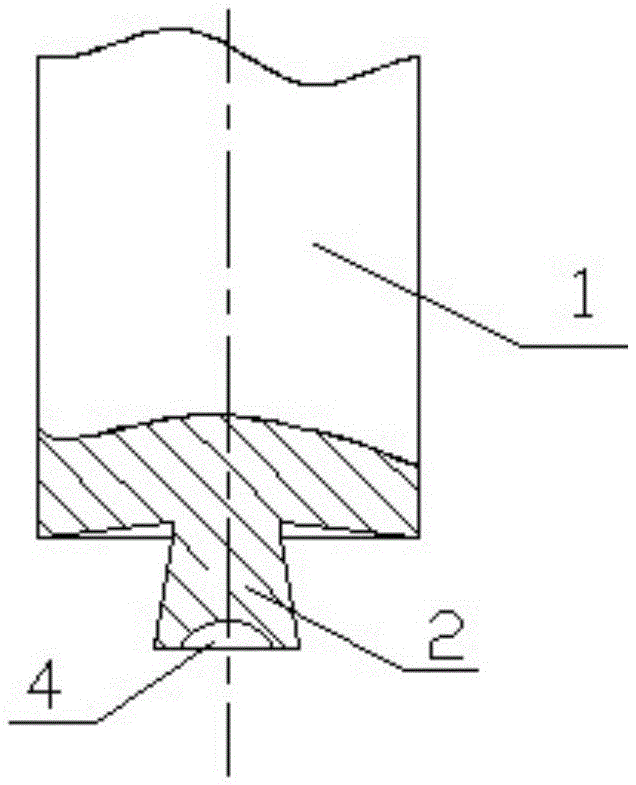
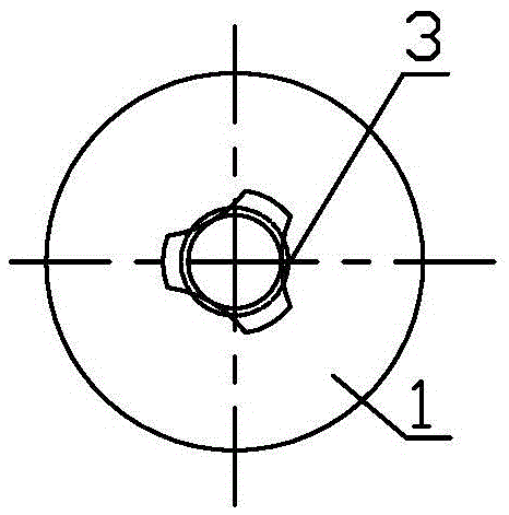
[0022] The length of setting stirring pin 2 is h=6mm, the cone angle 2α=16 ° of its truncated cone, and the (small bottom) top diameter of the truncated cone is D 2 =6mm, the diameter of the bottom (big bottom) is D 1 =2h*tanα+D 2 ≈7.7mm, the diameter of the circular concave hole 4 on the large bottom end face of the truncated cone is D 3 =0.75D 1 ≈5.8mm, depth h 1 = 1.5mm, the three arc-shaped grooves on the side of the stirring needle 2 are evenly distributed along the circumference, satisfying that the diameters of the three arc-shaped grooves 3 and the ci...


PUM

PropertyMeasurementUnit
diameteraaaaaaaaaa

Abstract

The invention discloses a friction stir welding tool for an overlap joint. The friction stir welding tool is composed of a shaft shoulder and a stirring needle. The stirring needle is shaped like a frustum, the small bottom of the frustum is connected with the shaft shoulder, the end face of the large bottom of the frustum is provided with a round concave hole, and the outer surface of the frustum is provided with three arc-shaped grooves distributed in the circumferential direction. Meanwhile, the invention further discloses the stirring needle and the structures and the sizes of all parts of the shaft shoulder. When a stirring tool designed through the friction stir welding tool is adopted for carrying out friction stir overlap welding, the stirring needle of the frustum shape generates oblique upward thrust on plasticized metal around the overlap face, so that the perpendicular motion of the plasticized metal is reduced, and the perpendicular moving tendency of the overlap face is reduced. Moreover, as the concave hole and the grooves in the side face are formed in the bottom of the stirring needle, material flow in weld zones is improved, the overlap face is broken completely, and the weld metal can be mixed fully. Accordingly, the size of the hook-like defect in a weld joint obtained through welding of the tool is greatly reduced, and the strength coefficient of the joint is remarkably improved.

Description

technical field [0001] The invention belongs to the field of friction stir welding of metal materials, in particular to a novel friction stir welding tool designed for lap joints. Background technique [0002] Friction stir welding (FSW) is a new type of solid-phase joining technology invented by the British Welding Institute (TWI) in 1991. This technology is especially suitable for the joining of non-ferrous metals such as aluminum-magnesium alloys. The basic principle of friction stir welding is that a rotating non-consumable stirring tool (a stepped shaft composed of a shaft shoulder and a stirring needle) is inserted into the joint surface of the workpiece, and heat is generated through the friction between the shoulder and the workpiece and the stirring needle and the workpiece The plastic deformation of the material produces heat, and the workpiece to be welded is heated to a plasticized state, and the joint surface of the workpiece will be broken under the stirring fr...

Claims


Application Information

Patent Timeline
Patent Type & Authority Patents(China)
IPC IPC(8): B23K20/12
CPCB23K20/1255
Inventor 宋友宝杨新岐
Owner TIANJIN UNIV
Why Eureka
Try Eureka