
Semi-automatic welding device for circumferential welds

A semi-automatic welding and annular welding technology, applied in the direction of auxiliary equipment, welding equipment, auxiliary welding equipment, etc., can solve the problems of high cost, low efficiency, low welding quality, etc., achieve uniform feeding, ensure voltage, and improve production efficiency effect

Inactive Publication Date: 2015-06-17
XUZHOU BAISHILI ELECTRIC VEHICLE +1
View PDF6 Cites 0 Cited by
  • Summary
  • Abstract
  • Description
  • Claims
  • Application Information

AI Technical Summary

Problems solved by technology

Due to its low welding quality and low efficiency, manual welding devices are gradually replaced by semi-automatic welding devices and fully automatic welding devices
However, since the automatic welding device is mainly a complete set of equipment, it is more suitable for mass production, and the cost is relatively high.

Method used


Image

  • Semi-automatic welding device for circumferential welds
  • Semi-automatic welding device for circumferential welds

Examples


Embodiment Construction

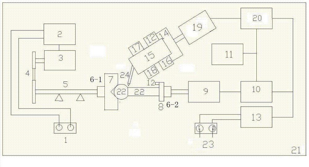
[0025] Such as figure 1 As shown, the present invention consists of a motor controller 2, an electromagnetic speed regulating motor 3, a transmission device 4, a main shaft 5, a first turntable mechanism, a second turntable mechanism, a positioning mechanism 7, a clamping mechanism 8, a No. 1 cylinder 9, and a No. 1 cylinder. Electromagnetic control valve 10, air pump 11, travel switch 12, control mechanism 13, clamping sleeve 14, welding torch 15, limit block 16, wire feeding mechanism 17, time relay 18, No. 2 cylinder 19, No. 2 electromagnetic control valve 20, And frame 21 forms.

[0026] The working process of this system is as follows:

[0027] (1) Position the spherical workpiece 22 to be processed on the positioning mechanism 7, adjust the position of the limit block 16 according to the specifications of the workpiece to be processed, pull the wrench I of the switch 23 of the control device to turn to the left, and the control device 13 passes through No. The electro...


PUM


Abstract

The invention relates to a semi-automatic welding device for circumferential welds. The semi-automatic welding device comprises a motor controller, an electromagnetic speed adjusting motor, a locating mechanism, a clamping mechanism, a first air cylinder, a first electromagnetic control valve, an air pump, a travel switch, a control mechanism, a second air cylinder, a second electromagnetic control valve and the like. The control mechanism controls the amount of air pumped to the first air cylinder through the first electromagnetic control valve, the first air cylinder pushes the clamping mechanism to move in the direction towards the locating mechanism through a rotary disc mechanism, and after signals for triggering the travel switch are detected, the clamping mechanism stops moving towards the locating mechanism. The motor controller controls the rotation speed of the electromagnetic speed adjusting motor, the locating mechanism and the clamping mechanism synchronously rotate, the control mechanism controls the amount of air pumped to the second air cylinder through the second electromagnetic control valve, the second air cylinder pushes a welding gun to move, and when the welding gun moves to a limiting block, the travel switch is triggered, and the welding gun stops moving. The semi-automatic welding device is prone to guaranteeing the welding quality, high in welding efficiency, low in cost and simple in structure.

Description

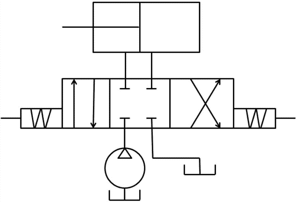
technical field [0001] The invention relates to a welding device, in particular to a semi-automatic ring welding seam welding device which combines an air pressure system, an electrical system and a mechanical system. The invention is not only suitable for pneumatic systems, but also suitable for hydraulic systems. If the present invention adds a set of automatic loading and unloading workpiece mechanism, fully automatic welding can be realized. technical background [0002] At present, there are many types of welding devices, classified according to the operation mode, mainly including manual welding devices, semi-automatic welding devices and fully automatic welding devices. Due to its low welding quality and low efficiency, manual welding devices are gradually replaced by semi-automatic welding devices and fully automatic welding devices. However, since the fully automatic welding device is mainly a complete set of equipment, it is more suitable for mass production, and...

Claims


Application Information

Patent Timeline
Patent Type & Authority Patents(China)
IPC IPC(8): B23K37/04B23K37/00B23K37/02
CPCB23K37/00B23K37/0247B23K37/0252B23K37/027B23K37/047
Inventor 冯能莲康常涛郭陈栋
Owner XUZHOU BAISHILI ELECTRIC VEHICLE
Learn More