Special numerical control machine tool for milling end face, drilling center hole and lathing outer circle of thin and long shaft part

A technology for drilling center holes and CNC machine tools, which is applied in the field of CNC machine tools, can solve the problems of easy deformation of workpieces, precision, long time consumption, and high scrap rate, and achieve the effects of high time utilization, high machining accuracy, and low scrap rate

Inactive Publication Date: 2014-01-22
沈阳市大鑫数控机械有限责任公司
View PDF0 Cites 17 Cited by
  • Summary
  • Abstract
  • Description
  • Claims
  • Application Information

AI Technical Summary

Problems solved by technology

[0002] At present, when processing slender piston rod parts in special equipment in the petroleum field, ordinary lathes are used for processing. The three processes of milling, drilling, and turning require two clamping. When clamping, the worker manually clamps and adjusts the center position. Mill the end face and then drill the center hole. When drilling, it is necessary to manually withdraw the turning tool holder from the original working position, and manually rotate the tailstock to realize drilling. After completing the drilling process, it is necessary to stop the machine and manually release the chuck. The part is extended according to the length of the turned outer circle and then clamped, and the tailstock is manually withdrawn from the original working position, and then the outer circle of the part is turned. The whole process takes a long time, the efficiency is low, and the workpiece is easily deformed and the accuracy is very low. Difficult to guarantee, high scrap rate

Method used


Image

  • Special numerical control machine tool for milling end face, drilling center hole and lathing outer circle of thin and long shaft part
  • Special numerical control machine tool for milling end face, drilling center hole and lathing outer circle of thin and long shaft part
  • Special numerical control machine tool for milling end face, drilling center hole and lathing outer circle of thin and long shaft part

Examples


Embodiment Construction

[0060] The present invention will be further described in detail through the drawings and examples below. From these descriptions, the features and advantages of the present invention will become more apparent.

[0061] The word "exemplary" is used exclusively herein to mean "serving as an example, embodiment, or illustration." Any embodiment described herein as "exemplary" is not necessarily to be construed as superior or better than other embodiments. While various aspects of the embodiments are shown in drawings, the drawings are not necessarily drawn to scale unless specifically indicated.

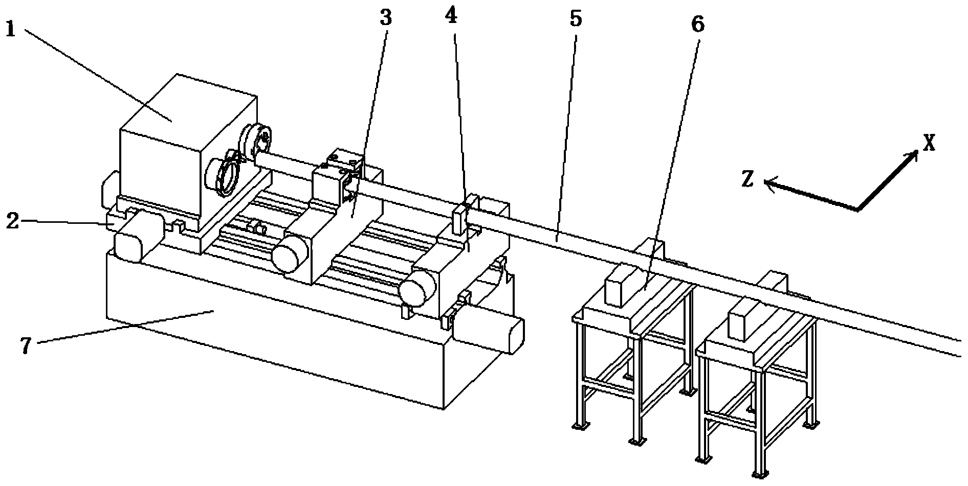
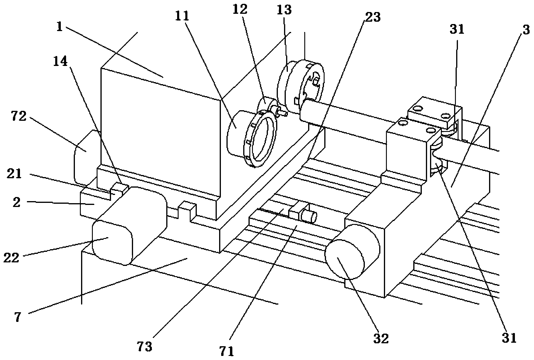
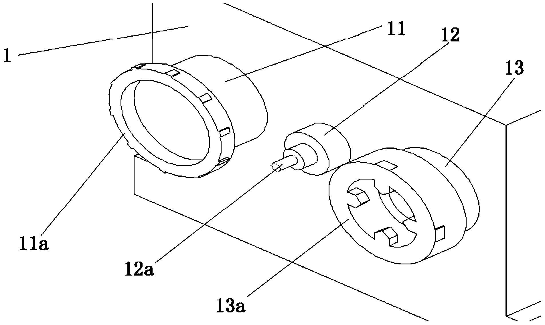
[0062] In a preferred embodiment of the present invention, such asfigure 1 , 2 As shown in and 4, special CNC machine tools for milling end faces, drilling center holes, and turning outer circles of slender shaft parts are provided. The CNC machine tools include:

[0063] The spindle box 1, the spindle box base 2, the clamping and guiding device 3, the clamping and feeding device 4,...


PUM


Abstract

The invention relates to a special numerical control machine tool for milling an end face, drilling a center hole and lathing an outer circle of a thin and long piston rod part of a special device in the filed of petroleum, in particular to a special numerical control machine tool for milling an end face, drilling a center hole and lathing an outer circle of a thin and long shaft part. The machine tool comprises a main shaft box, a main shaft box base, a clamping and guiding device, a clamping and feeding device, material supporting frames and a machine tool body. The main shaft box comprises three main shafts, namely the milling main shaft, the drilling main shaft and the lathing main shaft, and the main shaft box is supported on the main shaft box base which is connected with the machine tool body below. The clamping and feeding device is connected with the clamping and guiding device, wherein the clamping and feeding device and the clamping and guiding device clamp a workpiece together and perform workpiece feeding, and the material frames only play a role in supporting parts. According to the numerical control machine tool, three processes, namely milling the end face, drilling the center hole and lathing the outer circle of a thin and long shaft are finished through one-time clamping, the working efficiency is high, clamping, positioning, the feeding amount and the feeding speed are numerically controlled, the machining precision is high, and the rejection rate is low.

Description

technical field [0001] The invention relates to a special numerical control machine tool for milling the end face of the slender piston rod parts in special equipment in the petroleum field, drilling the center hole, and turning the outer circle. machine tool. Background technique [0002] At present, when processing slender piston rod parts in special equipment in the petroleum field, ordinary lathes are used for processing. The three processes of milling, drilling, and turning require two clamping. When clamping, the worker manually clamps and adjusts the center position. Mill the end face and then drill the center hole. When drilling, it is necessary to manually withdraw the turning tool holder from the original working position, and manually rotate the tailstock to realize drilling. After completing the drilling process, it is necessary to stop the machine and manually release the chuck. The part is extended according to the length of the turned outer circle and then cl...

Claims


Application Information

Patent Timeline
Patent Type & Authority Applications(China)
IPC IPC(8): B23P23/02
CPCB23P23/02
Inventor 柏新岩
Owner 沈阳市大鑫数控机械有限责任公司
Why Eureka
Try Eureka