Water plugging seepage-proofing method for recharge well

A technology for refilling wells and well pipes, which is applied to water supply devices, drinking water installations, protection devices, etc., can solve the problems of clogging failure of the filter layer of the refilling well, failure of the refilling well, and tilting of the well tube, so as to prevent the filter layer from being blocked. The effect of plugging failure, extending seepage path, extending hydraulic path

Active Publication Date: 2014-01-22
TIANJIN UNIV
View PDF5 Cites 2 Cited by
  • Summary
  • Abstract
  • Description
  • Claims
  • Application Information

AI Technical Summary

Problems solved by technology

But then the next failure occurs
[0006] (2) The filter layer of the reinjection well is clogged and fails
Although there are many reasons for the blockage of the filter layer of the reinjection well, after the measures in (1) are taken to block the water, before the cement slurry is solidified, the slurry may seep into the filter layer along the construction gap of the clay ball on the side of the well pipe
If during well construction, the reinjection well is accidentally disturbed and the well pipe is inclined, the possibility of this situation will be greatly increased
In fact, during construction, this kind of well pipe disturbance is unavoidable, especially when the well pipe is buried deep, which will also lead to the failure of the reinjection well

Method used


Image

  • Water plugging seepage-proofing method for recharge well
  • Water plugging seepage-proofing method for recharge well
  • Water plugging seepage-proofing method for recharge well

Examples


Embodiment Construction

[0041] In order to further understand the invention content, characteristics and effects of the present invention, the following examples are given, and detailed descriptions are as follows in conjunction with the accompanying drawings:

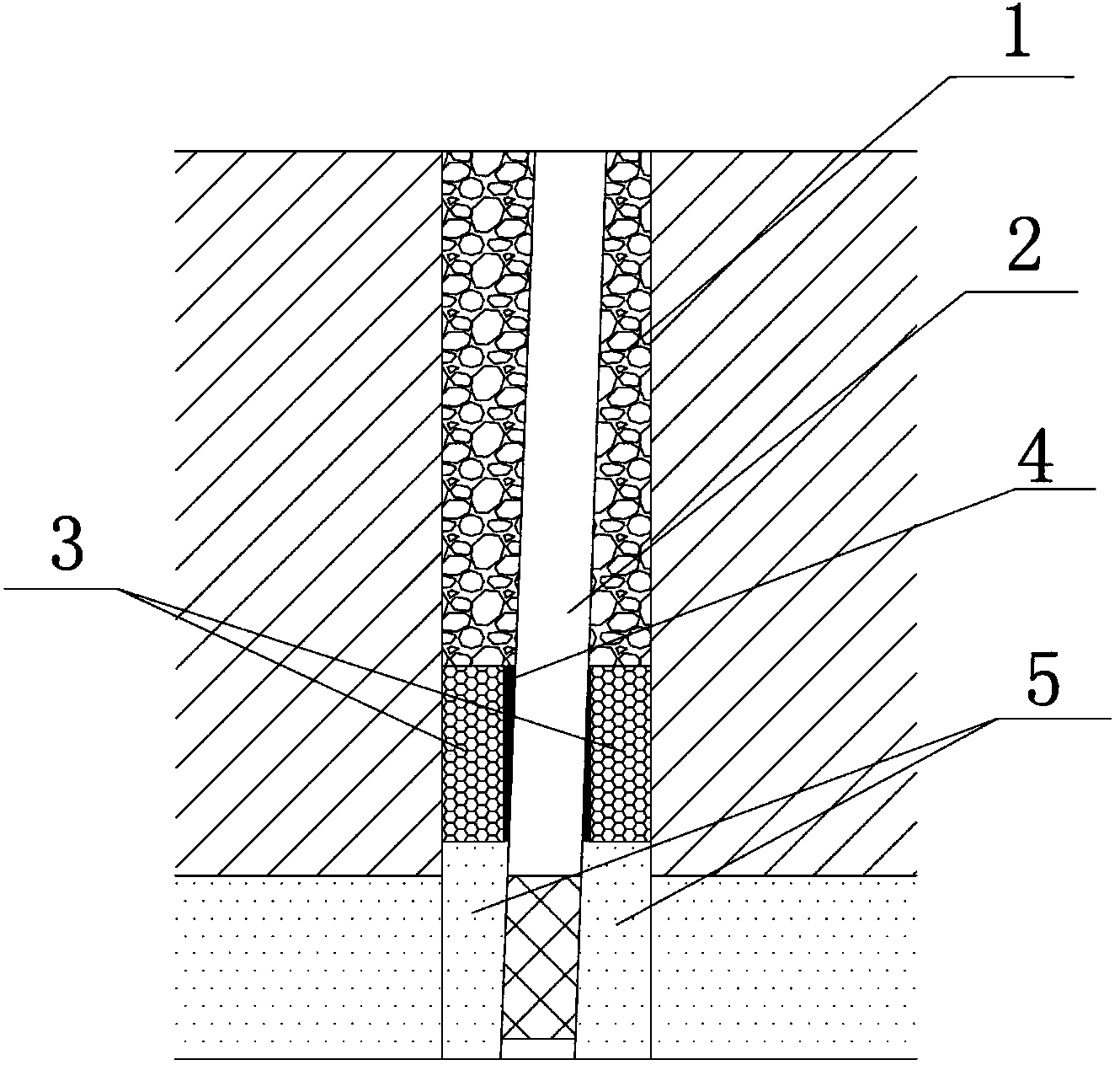
[0042] First, a brief introduction to the failure mode of water plugging and anti-seepage of conventional recharge wells. Such as figure 1As shown, during the well construction process, especially when the concrete water blocking layer 1 is applied, the concrete needs to be vibrated and compacted. Under the action of uneven or asymmetric vibration loads, the well pipe 2 is prone to sideways the tilt. On the one hand, since the clay ball water-resisting layer 3 is essentially a layer of cohesive soil with fine particles, its plasticity makes it have a certain shape before the well pipe 2 is not inclined, and after the well pipe 2 is inclined, when the water-resisting layer Before the medium clay balls have time to deform in the future, the u...


PUM


Abstract

The invention discloses a water plugging seepage-proofing method for a recharge well. The method includes the steps that firstly, a steel disc ring is premade, and a clamping groove is welded on a well casing in advance; a rubber balloon is placed in the clamping groove and pressurized, so that the clamping groove is filled with the rubber balloon, a sediment tube of the recharge well, a filter and the well casing are connected in a butt joint mode, fixed and then submerged in a well hole, and a gravel filter layer and a clay ball water resisting layer are constructed; the well casing is sleeved with the steel disc ring, the steel disc ring is submerged to the well hole, when the reading number of a pressure measuring instrument is synchronously increased along with the submergence of the steel disc ring, deflation and pressure reduction are conducted on the rubber balloon, the steel disc ring is quickly submerged until the steel disc ring can not continue submerging, the lower portion of the steel disc ring is pressed in the clamping groove, the rubber balloon is extruded in the gap between the clamping groove and the steel disc ring, and eventually a concrete water plugging layer is constructed. According to the method, plugging failure of the filter layer caused by inevitable well casing disturbance in the well completion construction process and recharge water upwelling in the running process of the recharge well can be effectively avoided, even inclination of the well casing can be reduced or avoided, and by the cooperation of other recharge water preprocessing measures, eventually normal working of the recharge well can be guaranteed.

Description

technical field [0001] The invention belongs to the field of foundation pit dewatering by using recharge to control ground subsidence, or the field of groundwater resources management and the field of groundwater treatment, and more specifically relates to a water blocking and anti-seepage method in a recharge well. Background technique [0002] During the excavation of the foundation pit, the problem of controlling the confined water is often encountered. It is common practice to use depressurization wells to depressurize confined aquifers. At the same time, in order to reduce the impact of precipitation in the pit on the environment outside the pit, water-proof curtains are often used to cut off the confined aquifer. However, as the excavation depth of the foundation pit increases, the confined aquifer that needs to be controlled becomes deeper and deeper. At this time, if the water-proof curtain is still used to cut it off, the depth of the water-proof curtain will reach...

Claims


Application Information

Patent Timeline
Patent Type & Authority Applications(China)
IPC IPC(8): E02D31/02E03B3/34
Inventor 郑刚曾超峰
Owner TIANJIN UNIV
Why Eureka
Try Eureka