Injection type refrigerating machine with middle heat exchanging part

An intermediate heat exchange and injection technology, which is used in refrigerators, machines using refrigerant evaporation, refrigeration and liquefaction, etc., can solve the problems of complex structure and high operating costs, and achieve the effect of improving the cooling coefficient and reducing the load.

Active Publication Date: 2014-01-22
NINGBO INST OF TECH ZHEJIANG UNIV ZHEJIANG
View PDF7 Cites 22 Cited by
  • Summary
  • Abstract
  • Description
  • Claims
  • Application Information

AI Technical Summary

Problems solved by technology

However, the above-mentioned refrigeration system uses a rectification tower as a separation device, which has a complex structure and high operating costs.

Method used


Image

  • Injection type refrigerating machine with middle heat exchanging part
  • Injection type refrigerating machine with middle heat exchanging part
  • Injection type refrigerating machine with middle heat exchanging part

Examples


Embodiment 1

[0029] Such as figure 1 As shown, an ejector refrigerator with intermediate heat exchange components includes a first throttling element 1, an evaporator 2, a first ejector 3, a second ejector 4, a condenser 5, and a second throttling element 6 , subcooler 7, circulation pump 8, first generator 9.

[0030] The working fluid inlets of the first injector 3 and the second injector 4 and the working fluid outlet of the first generator 9 (in the present invention, "working fluid outlet" and "exit" all represent the same concept unless otherwise specified. ) communication, the injection fluid inlet of the first injector 3 is connected with the working medium outlet of the evaporator 2, the working medium outlet of the first injector 3 is connected with the injection fluid inlet of the second injector 4, and the second injection The working medium outlet of the condenser 4 is connected with the working medium inlet of the condenser 5; between the working medium outlet of the condens...

Embodiment 2

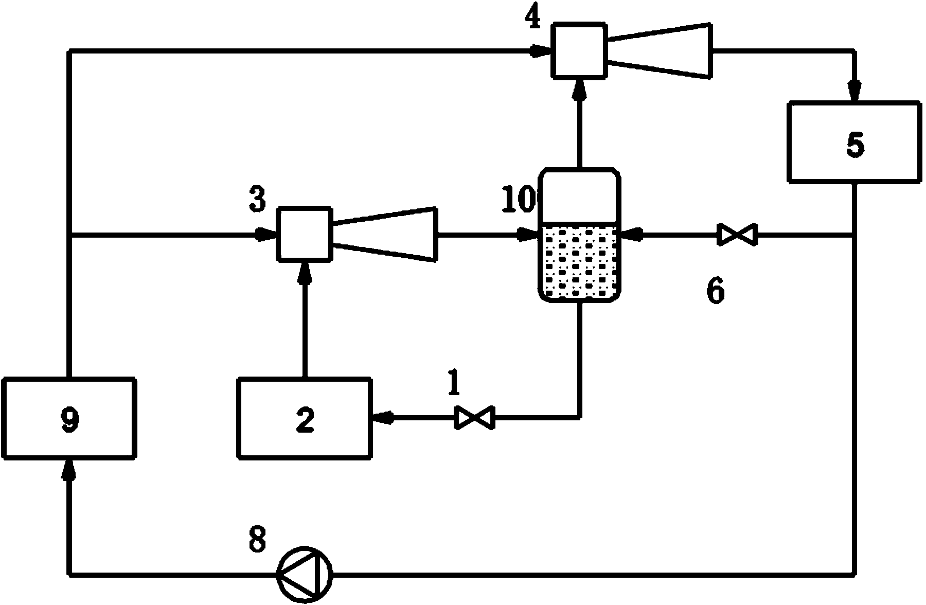
[0034] Such as figure 2 As shown, an ejector refrigerator with intermediate heat exchange components includes a first throttling element 1, an evaporator 2, a first ejector 3, a second ejector 4, a condenser 5, and a second throttling element 6 , Economizer 10, circulation pump 8, first generator 9.

[0035] The gas-phase working medium outlet of the economizer 10 is connected with the injection fluid inlet of the second injector 4; the working medium outlet of the first injector 3, the working medium outlet of the second throttling element 6 and the working medium inlet of the economizer 10 The liquid-phase working medium outlet of the economizer 10 is connected with the working medium inlet of the first throttling element 1; at this time, a part of the working medium liquid at the outlet of the condenser 5 is throttled by the second throttling element 6 and becomes an intermediate pressure The lower two-phase state is mixed with the working fluid at the outlet of the first...

Embodiment 3

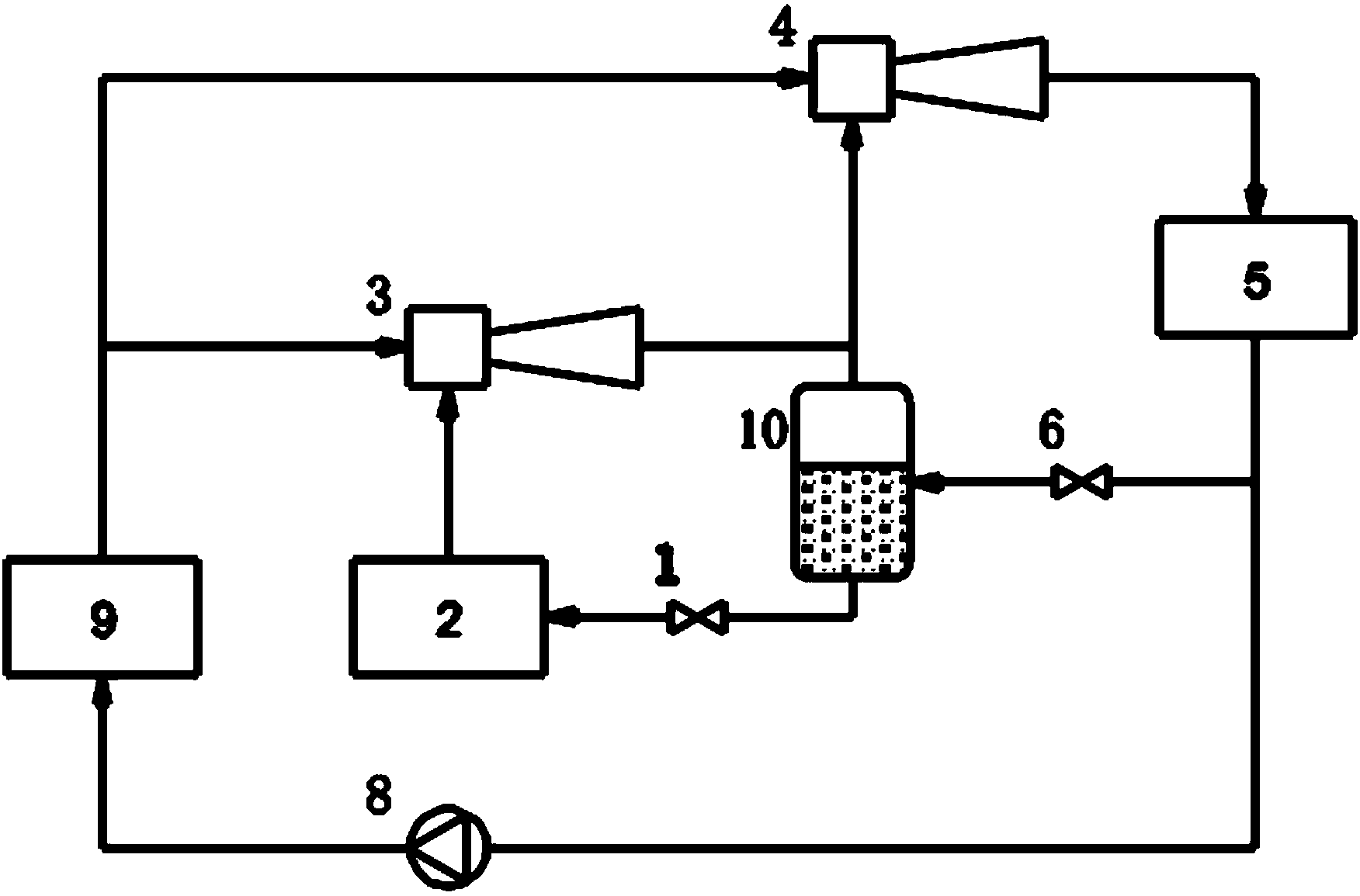
[0037] Such as image 3 As shown, an ejector refrigerator with intermediate heat exchange components includes a first throttling element 1, an evaporator 2, a first ejector 3, a second ejector 4, a condenser 5, and a second throttling element 6 , Economizer 10, circulation pump 8, first generator 9.

[0038] The gas-phase working medium outlet of the economizer 10 is connected with the injection fluid inlet of the second injector 4; the working medium outlet of the second throttling element 6 is connected with the working medium inlet of the economizer 10; the liquid-phase working medium of the economizer 10 The outlet of the refrigerant is connected with the inlet of the working fluid of the first throttling element 1; at this time, a part of the working fluid at the outlet of the condenser 5 is throttled by the second throttling element 6 and becomes a two-phase state under intermediate pressure. 10 is divided into two phases of gas and liquid, the gas phase working medium ...


PUM


Abstract

The invention discloses an injection type refrigerating machine with a middle heat exchanging part. The injection type refrigerating machine with the middle heat exchanging part comprises a first restricting element, an evaporator, a first ejector, a second ejector, a condenser, a second restricting element, a subcooler or an economizer, a circulating pump and a first generator, wherein a working fluid inlet of the first ejector and a working fluid inlet of the second ejector are communicated with a working medium outlet of the first generator, a driving fluid inlet of the first ejector is communicated with a working medium outlet of the evaporator, a working medium outlet of the first ejector is communicated with a driving fluid inlet of the second ejector, and a working medium outlet of the second ejector is communicated with a working medium inlet of the condenser. The injection type refrigerating machine with the middle heat exchanging part has the advantages that constraint of traditional thought is broken through; due to the fact that the middle heat exchanging part such as the economizer or the subcooler is adopted, gas phase working media of the economizer or the subcooler can directly enter the second ejector and do not need to be compressed again through the first ejector, then the load of the first ejector is reduced, and the refrigeration coefficient of a system is improved.

Description

technical field [0001] The invention belongs to the technical field of refrigeration, in particular to an ejector refrigerator with an intermediate heat exchange component. Background technique [0002] Ejection refrigeration technology is a heat-driven refrigeration technology. Compared with mechanical compression refrigeration technology, its main advantage is that it only consumes little mechanical energy and can directly use heat energy as the driving energy. It has the advantages of simple structure, small size and low cost. Low cost, reliable operation, long service life and other advantages. Jet refrigeration is a refrigeration method driven by low-grade energy, which can effectively utilize renewable energy such as solar energy and geothermal energy, as well as industrial waste heat and waste heat; the refrigerant used in jet refrigeration is mainly water, hydrocarbons or hydrofluorine Hydrocarbon refrigerants can avoid the use of CFCs or HCFCs refrigerants that des...

Claims


Application Information

Patent Timeline
Patent Type & Authority Applications(China)
IPC IPC(8): F25B19/02F25B40/00
Inventor 陈光明陈少杰杨申音林玮
Owner NINGBO INST OF TECH ZHEJIANG UNIV ZHEJIANG
Why Eureka
Try Eureka