Stall detection of wind turbine blades

A wind turbine and detector technology, which is applied in the control of wind turbines, monitoring of wind turbines, wind turbines, etc., can solve problems such as reducing the power output of wind turbines, and achieve the effect of reducing stall and improving power production.

Inactive Publication Date: 2014-01-22
SIEMENS AG
View PDF0 Cites 7 Cited by
  • Summary
  • Abstract
  • Description
  • Claims
  • Application Information

AI Technical Summary

Problems solved by technology

This causes two problems: the control law may be too conservative for many situations and unnecessarily reduces the power output of the wind turbine

Method used


Image

  • Stall detection of wind turbine blades
  • Stall detection of wind turbine blades
  • Stall detection of wind turbine blades

Examples


Embodiment Construction

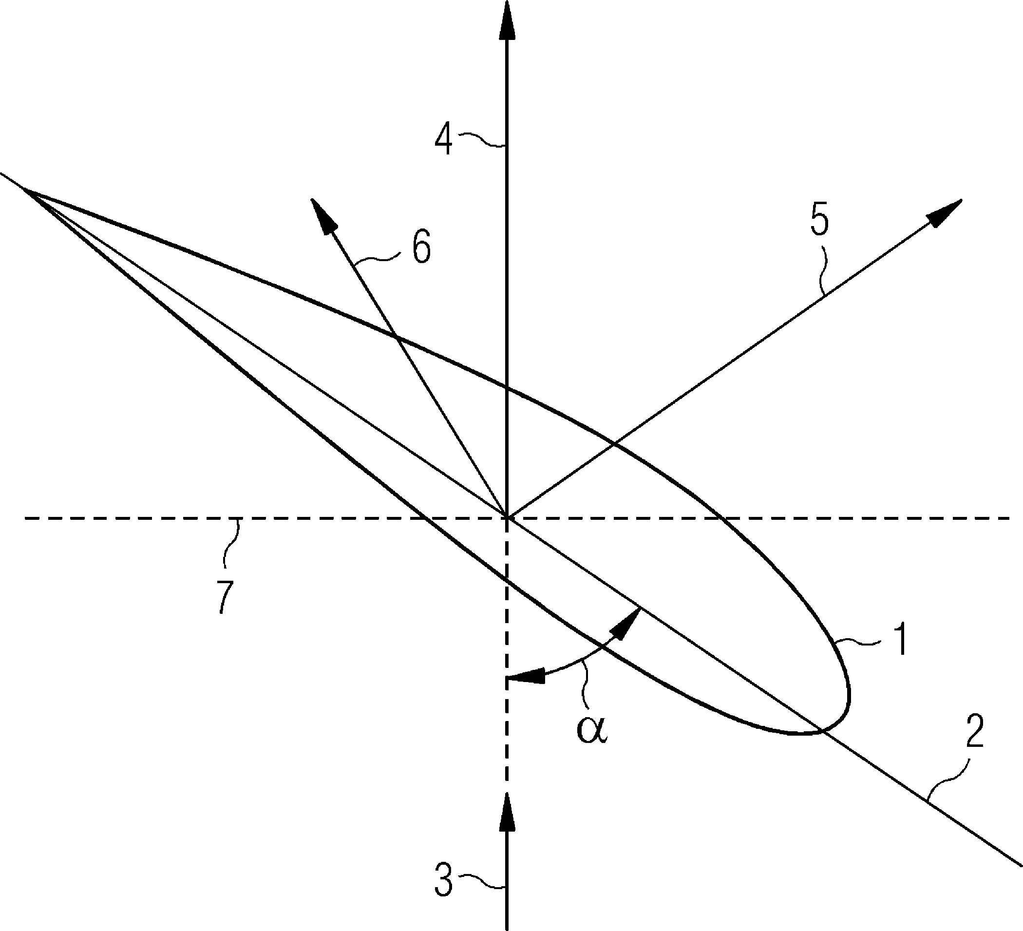
[0022] figure 1 An exemplary airfoil 1 of a rotor blade of a wind turbine is shown. The angle of attack α is measured between the chord line 2 of the airfoil 1 and the wind direction 3 . The corresponding pitch angle measured between the chord line 2 and the plane 7 of rotation can be used to describe the orientation of the rotor blade 1 . The chord line 2 intersects the leading and trailing edges of the airfoil 1 . Wind 3 acting on the airfoil 1 moves the rotor blade along the plane 7 of rotation. As the rotor blades rotate due to the rotor effective wind speed, the rotor blades experience an additional wind speed component opposite the direction of rotation. Thus, the blade experiences a wind speed as a result of the wind direction as seen by the rotating rotor blade.

[0023] Due to the profile of the rotor blade, a pressure drop is generated on the upper surface of the rotor blade, which pressure drop generates a lift force 5 perpendicular to the resulting wind speed. ...


PUM


Abstract

The invention provides a stall sensor for a wind turbine, a wind turbine comprising such a stall sensor and a method of operating such a wind turbine. The stall sensor comprises detector means (10) adapted to measure vibration of a rotor blade of the wind turbine and to output a vibration signal representative of the vibration of the rotor blade, conversion means (11) connected to the detector means (10) and adapted to determine a noise figure representative of a spectral signal content within a frequency band of the vibration signal received from the detector means (10) and arbiter means (12) connected to the conversion means (11) and adapted to signal a presence or an absence of stall based on the noise figure received from the conversion means (11).

Description

technical field [0001] The invention relates to a stall sensor for a wind turbine, a wind turbine comprising such a stall sensor and a method of operating such a wind turbine. Background technique [0002] The wind turbines are controlled to maximize power output, to reduce load and wear on the wind turbines and to reduce acoustic noise emissions. Controllers for wind turbines are designed to provide good performance for certain environmental conditions. When the control strategy is determined, the aerodynamic capabilities are pushed to their limits in the power-optimized region to maximize the performance of the wind turbine. However, if the aerodynamic settings are too aggressive, e.g. because of inaccuracies in the model used to arrive at the settings, changes in environmental conditions, etc., the blades of the wind turbine may stall and suddenly the power output will drop and the load and Noise will be significantly improved. [0003] The lift force of a wind turbine...

Claims


Application Information

Patent Timeline
Patent Type & Authority Applications(China)
IPC IPC(8): G01H17/00G01B21/00G01P15/00
CPCF03D7/028Y02E10/723F03D7/0292Y02E10/722F05B2260/96F03D7/0256F05B2270/334F03D11/0091F03D7/0224F03D7/0296F05B2270/333F03D17/00Y02E10/72
Inventor T.埃斯本森G.赫格
Owner SIEMENS AG
Why Eureka
Try Eureka