Cavity for magneto-optical trap reaction microscope imaging spectrometers

A technology of microscopic imaging and magneto-optical traps, applied in spectrometry/spectrophotometry/monochromators, instruments, scientific instruments, etc., can solve the problem of reducing the resolution of atomic and molecular imaging experiments, resolution cannot be completely solved, Blur the inherent physical image and other problems to achieve the effect of ensuring stability and space-time aggregation characteristics, improving imaging resolution, and optimizing electric field

Inactive Publication Date: 2014-01-22
SHANGHAI ADVANCED RES INST CHINESE ACADEMY OF SCI
View PDF4 Cites 6 Cited by
  • Summary
  • Abstract
  • Description
  • Claims
  • Application Information

AI Technical Summary

Problems solved by technology

[0005] At present, many-body coincidence imaging experiments generally use supersonic gas targets. Although high-speed moving gas samples (atoms and molecules) can reduce the temperature of the gas to a certain extent, the thermal motion of gaseous atoms and molecules still exists, which greatly reduces the temperature of the atoms. The energy (momentum) resolution of molecular imaging experiments makes it difficult to distinguish the quantum state in the energy representation (momentum distribution), blurring the internal physical image
[0006] In addition, other frontier scientific issues in atomic and molecular physics, such as highly excited state quantum chaos induced by electron-electron correlation in many-body dynamics, double-electron ionization correlation entanglement, and the internal physical mechanism of attosecond high-order harmonic generation, are also limited by the current resolution. and cannot be completely resolved

Method used


Image

  • Cavity for magneto-optical trap reaction microscope imaging spectrometers
  • Cavity for magneto-optical trap reaction microscope imaging spectrometers

Examples


Embodiment Construction

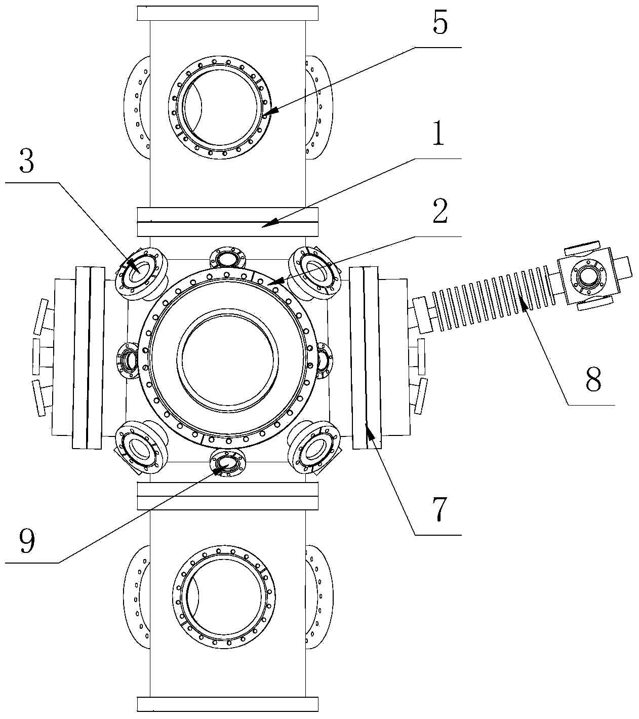
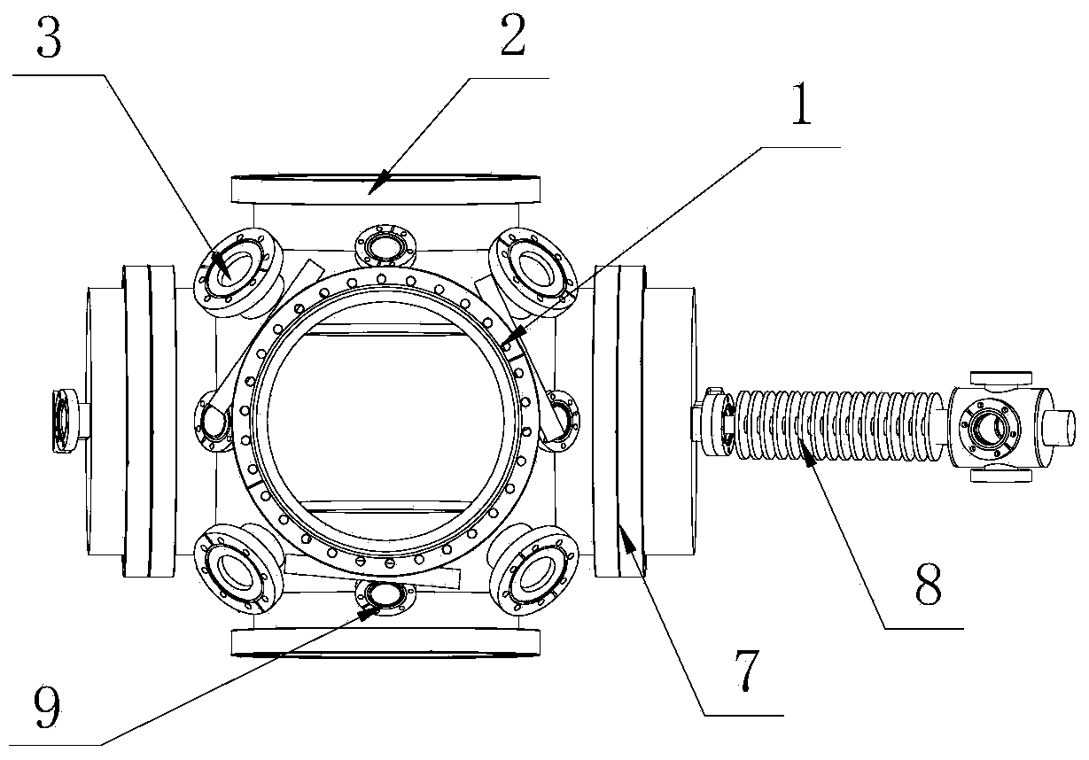
[0030] Such as figure 1 , figure 2 As shown, the cavity of the magneto-optical trap reaction microscopy imaging spectrometer of the present invention includes a spherical cavity, and the upper and lower ends (Z direction) of the spherical cavity are respectively connected to a cylindrical cavity through a side flange 1, and two The cylindrical cavity is on the same axis and communicates with the inner cavity of the spherical cavity; the side wall of each cylindrical cavity is evenly distributed with three flanges 5 along the circumference; the cylindrical cavity is used to connect ion or electron detection device; flange 5 is used for external vacuum pump system or as an observation window;

[0031] The left and right (X direction) ends of the spherical cavity are respectively opened and connected to the side flange 7; one of the side flanges 7 is connected to one end of the Zeeman slower (Zeeman slower) 8, and the other end of the Zeeman slower 8 is connected to the atom S...


PUM


Abstract

The invention discloses a cavity for magneto-optical trap reaction microscope imaging spectrometers, which comprises a spherical cavity; the upper end and lower end of the spherical cavity are respectively connected with a cylindrical cavity through a side flange; the left end and right end of the spherical cavity are respectively holed and connected with a side flange; one side flange is connected with one end of a Zeeman slower, and the other end of the Zeeman slower is connected with an atom steamer; a plurality of copper plates for dissipating heat are sleeved on the Zeeman slower, and a magnetic coil is wound on the copper plates; the front end and rear end of the spherical cavity are respectively holed and connected with a side flange as an optical window; at least sixteen flange ports as beam input windows or observation windows are evenly distributed on the remaining part of the spherical cavity, and the central axis of each flange port intersects the center of the spherical cavity; and a magneto-optical trap is fixed in the spherical cavity, and is used for cooling and confining target atoms. The cavity is integrated with the respective advantages of the magneto-optical trap technology and a reaction microscope imaging spectrometer, thus broadening the application range of reaction microscope imaging.

Description

technical field [0001] The invention relates to a reaction microscopic imaging spectrometer, in particular to a cavity of a magneto-optical trap reaction microscopic imaging spectrometer. Background technique [0002] In recent years, the new technology of ultra-strong and ultra-fast lasers and a new generation of synchrotron radiation sources has been developed unprecedentedly. Attosecond high-order harmonics, third-generation synchrotron radiation (Shanghai Advanced Light Source) and free electron laser (fourth-generation synchrotron radiation) have triggered a new technology revolution of extremely strong field ultrafast lasers, new physics and new effects of their interaction with matter , quantum coherent control of ultrafast electrons, atomic and molecular reaction dynamics, precision measurement and regulation under extreme conditions and other key scientific issues in the fields of atomic molecular information, condensed matter, semiconductor materials, space, biomed...

Claims


Application Information

Patent Timeline
Patent Type & Authority Applications(China)
IPC IPC(8): G01J3/02
Inventor 江玉海刘亦帆张逸竹朱干军
Owner SHANGHAI ADVANCED RES INST CHINESE ACADEMY OF SCI
Why Eureka
Try Eureka