Control method of topology variable grid-connected inverter

A control method and inverter technology, which are applied in the same direction of converting irreversible DC power input into AC power output, can solve the problems of low working efficiency of grid-connected inverters

Inactive Publication Date: 2014-01-22
HARBIN INST OF TECH
View PDF7 Cites 14 Cited by
  • Summary
  • Abstract
  • Description
  • Claims
  • Application Information

AI Technical Summary

Problems solved by technology

[0003] The invention aims to solve the problem of low working efficiency of the grid-connected inverter in the traditional grid-connected inverter control method. The invention provides a control method of the topology-variable grid-connected inverter

Method used


Image

  • Control method of topology variable grid-connected inverter
  • Control method of topology variable grid-connected inverter
  • Control method of topology variable grid-connected inverter

Examples


specific Embodiment approach 1

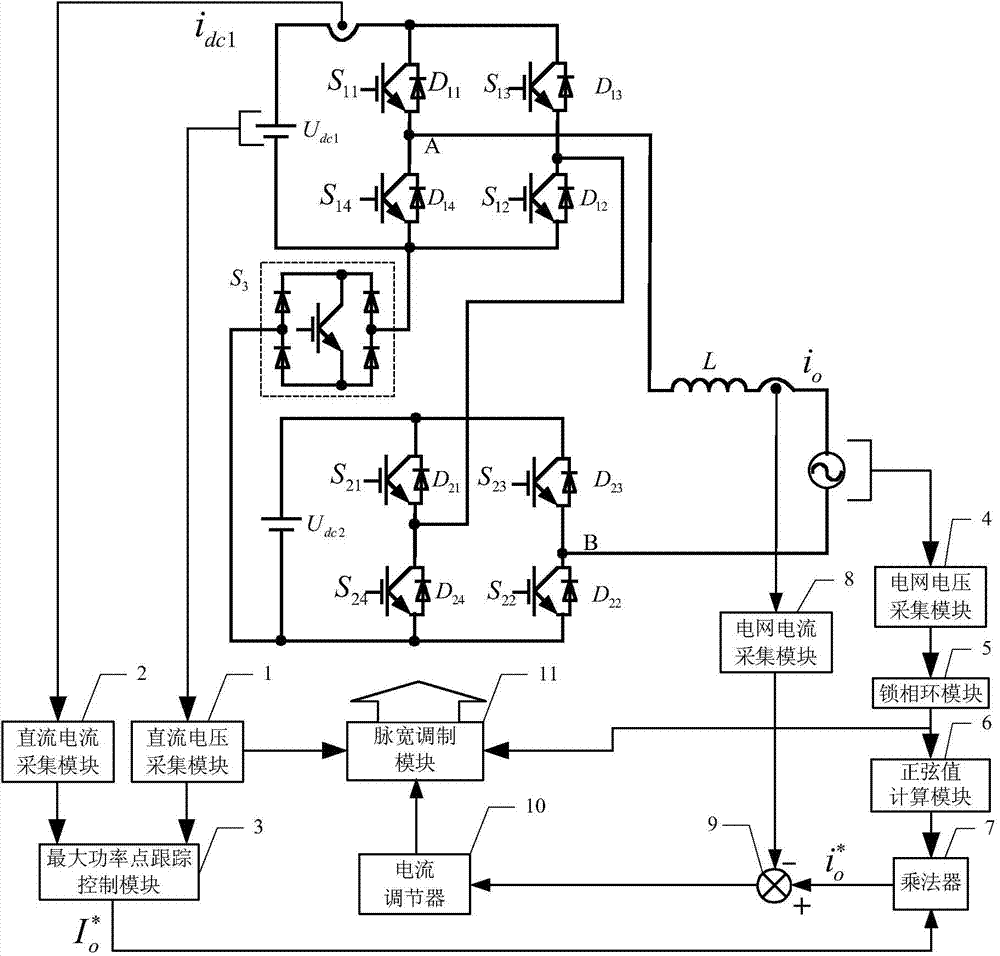
[0042] Specific embodiment one: see figure 1 , 2 And 3 illustrate this embodiment, the control method of a topology variable grid-connected inverter described in this embodiment is based on a topology variable grid-connected inverter, and the topology variable parallel The grid inverter includes a first DC power supply U dc1 , The second DC power supply U dc2 , The first power switch S 11 , The first diode D 11 , The second power switch S 12 , The second diode D 12 , The third power switch S 13 , The third diode D 13 , The fourth power switch S 14 , The fourth diode D 14 , The fifth power switch S 21 , The fifth diode D 21 , The sixth power switch S 22 , The sixth diode D 22 , The seventh power switch S 23 , The seventh diode D 23 , The eighth power switch S 24 , The eighth diode D 24 , Two-way switch S 3 And filter inductor L;

[0043] The first DC power supply U dc1 The positive pole of the first power switch S 11 The power input terminal, the first diode D 11 The cathode, t...

specific Embodiment approach 2

[0058] Specific implementation manner 2: see figure 1 , 2 This embodiment is described with 3. The difference between this embodiment and the control method of a topology variable grid-connected inverter described in the first embodiment is that the current regulator 10 in step 4 is proportional-integral. Regulator.

specific Embodiment approach 3

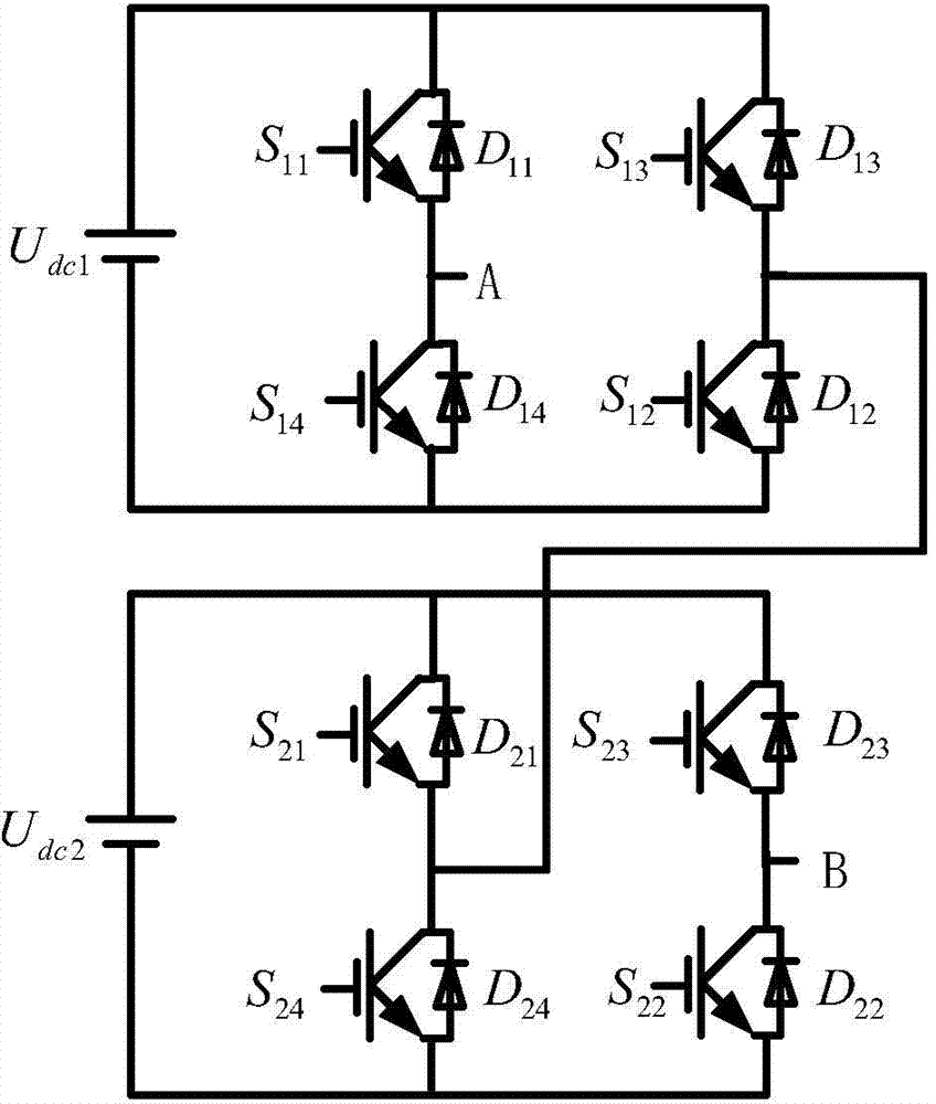
[0059] Specific implementation manner three: see figure 1 , 2 And 3 illustrate this embodiment. The difference between this embodiment and the control method of a topology variable grid-connected inverter described in specific embodiments 1 or 2 is that the topology variable grid-connected inverter in step 6 The inverter works in the cascaded inverter mode, and the rest of the power switches adopt the carrier phase-shifted multi-level sine wave pulse width modulation strategy for control. The specific process is based on the instantaneous value of the inverter voltage obtained in step 4. It is compared with four triangular carriers with a certain phase difference, and the comparison result obtained is used as the control signal of the remaining power switches. The four triangular carriers with a certain phase difference are four triangular carriers with a mutual difference of 90 degrees in electrical angle. Tri1, Tri2, Tri3 and Tri4. Among them, the comparison result of the in...


PUM


Abstract

The invention discloses a control method of a topology variable grid-connected inverter, belongs to the field of electric energy conversion, and solves the problem of low working efficiency in the conventional grid-connected inverter control method. According to the topology variable grid-connected inverter disclosed by the invention, by adding a bidirectional switch, a cascade type inverter can be switched into a two-level inverter according to demands. Voltage and current of a direct current power supply on an input side are acquired, a set point of grid-connected current amplitude is obtained through a maximum power point track control algorithm, and a phase angle of the grid is obtained through a phase-locked loop module, a sine of the grid is obtained, is multiplied with the grid-connected current amplitude, and is input into a grid-connected current regulator together with a practical value of the grid-connected current, a reference modulating wave of the inverter is obtained, the reference modulating wave and the direct current power supply voltage on the input side are input into a pulse width modulating module together, so as to obtain control signals of a working mode and power switches of the topology variable grid-connected inverter. The control method is mainly used for controlling the topology variable grid-connected inverter.

Description

Technical field [0001] The invention belongs to the field of electric energy conversion. Background technique [0002] In today's world, issues such as energy shortage and deteriorating environment have received widespread attention. Photovoltaic power generation technology with clean, zero pollution characteristics provides a new development direction for solving energy problems. Because the photovoltaic power generation source is affected by the intensity of sunlight, its output voltage presents the characteristics of large fluctuations, and it is difficult to directly apply to grid-connected power generation. In order to solve the above problems, the two-stage conversion structure based on DC-DC-AC, the single-stage Z-source inverter structure and the multi-level power conversion structure are all applied in photovoltaic power generation systems. However, due to the large fluctuations of the output power of the photovoltaic power generation system, the grid-connected current...

Claims


Application Information

Patent Timeline
Patent Type & Authority Applications(China)
IPC IPC(8): H02M7/48H02M7/49
Inventor 骆素华吴凤江骆林松冯帆张陆捷
Owner HARBIN INST OF TECH
Why Eureka
Try Eureka