Method and vertical alignment device for installation and control of large-scale arc structure formwork
A technology of vertical alignment and arc structure, which is applied to the connection of formwork/formwork/work frame, the preparation of building components on site, and the construction of buildings, etc., which can solve the problem of inaccurate size control and inoperability of arc formwork. and other problems to achieve the effect of controlling template size, precise positioning and accurate measurement
- Summary
- Abstract
- Description
- Claims
- Application Information
AI Technical Summary
Problems solved by technology
Method used
Image
Examples
Embodiment 1
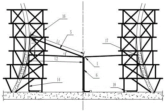
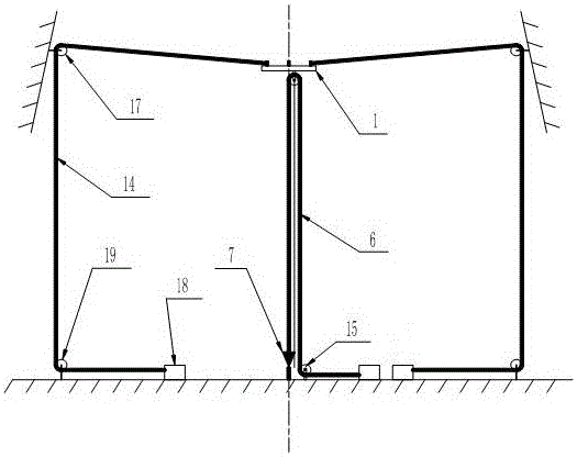
[0030] Such as figure 1 , figure 2 , image 3 , Figure 4 , Figure 7As shown, the method of installing and controlling large-scale arc-shaped structure templates determines and clearly marks the center point of the cooling tower, and makes a vertical centering device. The vertical centering device is set in the cooling tower and the center of the vertical centering device follows the The center points of the cooling tower coincide, and the vertical centering device is controlled by steel cables fixed in four directions in the shape of a cross. When positioning, four guide pulleys are fixed on the formwork support frame 16 that has been poured. 17. Set four directional pulleys 19 and 4 adjusting devices 18 on the ground, one end of one of the steel ropes is on the adjustment point of the vertical centering device, and the other end is wound around the directional pulley 17 and passes through the directional pulley 1 After the direction of 19 is adjusted, it is fixed with ...
Embodiment 2
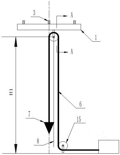
[0032] Such as image 3 , Figure 4 , the vertical centering device comprises a suspension pan 1, a connecting mechanism is installed on the top of the suspension pan 1, a pulley mechanism is fixed below the suspension pan 1, the pulley mechanism is connected with a steel wire rope 6 and a steel ruler 8, and the steel wire rope 6 is set on the pulley On the outer wall of the mechanism, one end of the steel wire rope 6 is connected with an adjustment device, and the other end is connected with a hanging hammer 7, and both the adjusting device and the hanging hammer 7 are arranged below the pulley mechanism, and the center line of the hanging hammer 7 and the center line of the hanging pan 1 set on the same straight line. The center line of the steel wire rope of the pulley 10 coincides with the center line of the hanging pan 1, and a hanging hammer 7 is tied under the steel wire rope 6, weighing about 40kg. The center of the hanging hammer 7 coincides with the center of the han...
Embodiment 3
[0034] Such as Figure 4 , Figure 5 As shown, on the basis of Embodiment 2, the pulley mechanism includes a pulley 10 and two steel plates 9, the two steel plates 9 are parallel to each other and the steel plates 9 are all welded on the bottom end surface of the suspension pan 1, and the pulley 10 is arranged on the two steel plates 9 Two bolts 11 are arranged between the steel plates 9, the two ends of the two bolts 11 pass through one of the steel plates 9 respectively, and the two bolts 11 pass through the pulley 10, the pulley 10 can rotate along the axis of the bolt two 11, and the steel wire rope 6 Set on the top wall surface of pulley 10, steel ruler buckle 2 13 is sleeved on the end of bolt 2 11, the top of steel ruler 2 8 is connected with the bottom end of steel ruler buckle 2 13, steel ruler 2 8 is arranged on steel wire rope 6 Between the two ends, steel ruler 2 8 is arranged on the outside of two steel plates 9. Bolt 2 11 is set under the suspension pan. In add...
PUM
 Abstract
Description
Claims
Application Information
 - R&D
- Intellectual Property
- Life Sciences
- Materials
- Tech Scout
- Unparalleled Data Quality
- Higher Quality Content
- 60% Fewer Hallucinations
Browse by: Latest US Patents, China's latest patents, Technical Efficacy Thesaurus, Application Domain, Technology Topic, Popular Technical Reports.
© 2025 PatSnap. All rights reserved.Legal|Privacy policy|Modern Slavery Act Transparency Statement|Sitemap|About US| Contact US: help@patsnap.com


