
Well cementation flushing fluid evaluation device and method based on principle of identical shearing rate

A technology of shear rate and flushing fluid, which is applied in the direction of flushing wellbore, earthwork drilling, wellbore/well components, etc., can solve the problems of cumbersome measurement steps, etc., and achieve the effect of real evaluation and real flushing efficiency

Active Publication Date: 2014-01-29
SOUTHWEST PETROLEUM UNIV +1
View PDF4 Cites 12 Cited by
  • Summary
  • Abstract
  • Description
  • Claims
  • Application Information

AI Technical Summary

Problems solved by technology

The device uses the rotating outer cylinder of the viscometer to simulate the stationary casing wall or well wall, which has the influence of rotating centrifugal force and the problem of not being able to simulate the formation of artificial cores to form mud cakes, and the measurement steps are cumbersome

Method used


Image

  • Well cementation flushing fluid evaluation device and method based on principle of identical shearing rate
  • Well cementation flushing fluid evaluation device and method based on principle of identical shearing rate
  • Well cementation flushing fluid evaluation device and method based on principle of identical shearing rate

Examples


Embodiment 1

[0058] Example 1 Flushing Efficiency Testing Experiment of Flushing Fluid to Well Wall or Casing

[0059] (1) A casing with an outer diameter of 139.70 mm is run in a wellbore with a diameter of 215.90 mm, and the drilling fluid is replaced at an average return velocity of the annular space of 0.5 m / s. When flushing with flushing fluid A for 8 minutes, evaluate the flushing of the well wall by flushing fluid A for 8 minutes washing efficiency.

[0060] In the first step, according to formula (1), the required rotational speed is 67.5r / min. In the second step, the artificial core is installed on the device of the present invention, and after the outer cylinder in the drilling fluid rotates at a speed of 67.5r / min for 30 minutes to form a mud cake, the core that forms the drilling fluid mud cake is removed and weighed to be 56.86g. The 3rd step, the rock core that forms mud cake is put back into the device of the present invention, replaces drilling fluid with flushing fluid A ...

Embodiment 2

[0063] Embodiment 2 flushing fluid system or formula optimal experiment

[0064] A casing with an outer diameter of 139.70 mm was run into a wellbore with a diameter of 215.90 mm, and the drilling fluid was replaced at an average annular velocity of 1.2 m / s. The flushing effects of the flushing fluids A, B and C were evaluated to select the flushing fluid.

[0065] When evaluating the advantages and disadvantages of various flushing fluids, one of the two, steel column or artificial core, can be used to simulate the flushing efficiency of casing or well wall. In this example steel columns are used for evaluation.

[0066] In the first step, according to formula (1), the required rotational speed is 162.0r / min. In the second step, the steel column is installed on the device of the present invention. After the outer cylinder in the drilling fluid rotates at a speed of 162.0r / min for 30 minutes to form a mud paste, remove the steel column adhering to the drilling fluid mud paste...

Embodiment 3

[0069] Implementation of 3 rinse solution dosage design

[0070] A casing with an outer diameter of 139.70 mm was run in a wellbore with a diameter of 215.90 mm, and the drilling fluid M was replaced by the average annulus return velocity of 0.8 m / s and 1.2 m / s respectively, and the reasonable dosage of flushing fluid S for these two return rates was designed.

[0071] In the first step, according to formula (1), the required speeds are 108.0r / min and 162.0r / min respectively when the return speed is 0.8m / s and 1.2m / s. In the second step, the artificial core is installed on the device of the present invention. After the outer cylinder in the drilling fluid rotates at a speed of 108.0r / min for 30 minutes to form a mud cake, the core that forms the drilling fluid mud cake is removed and weighed as 145.78g. The third step is to put the mud cake-forming rock core back into the device of the present invention, replace the drilling fluid with the flushing fluid S to be evaluated, and...


PUM


Abstract

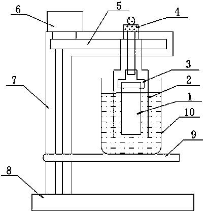
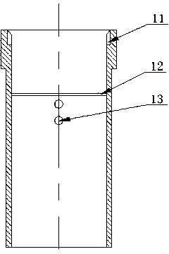
The invention discloses a well cementation flushing fluid evaluation device and method based on the principle of the identical shearing rate. The device is mainly composed of a manmade rock core or a steel pillar, an outer cylinder, a conversion adapter, a transmission device, a motor, a frame, a bearing plate and a thick liquid cup. The bearing plate and the motor are arranged on the frame. The thick liquid cup filled with flushing fluid is arranged on the bearing plate. The manmade rock core or steel pillar and the outer cylinder are located in the flushing fluid in the thick liquid cup. The manmade rock core or steel pillar is fixed on the frame through the conversion adapter. The outer cylinder is connected with the motor through the transmission device. The outer cylinder is provided with two rows of round holes for the flushing fluid to flow and the intervals of round holes of each row are 90 degrees. According to the well cementation flushing fluid evaluation device and method based on the principle of the identical shearing rate, the manmade rock core or the steel pillar is used for simulating a well wall and a casing pipe under a static state and the well cementation flushing fluid evaluation device and method are closer to engineering practice. The well cementation flushing fluid evaluation device and method based on the principle of the identical shearing rate have the advantages of being easy to operate, high in relative property and wide in application range and can measure the flushing efficiencies of a first interface and a second interface of well cementation by the flushing fluid respectively. According to the flushing efficiencies and the flushing time, a flushing fluid system is selected in an optimization mode and the use amount of the flushing fluid is designed. The well cementation flushing fluid evaluation device and method based on the principle of the identical shearing rate have the wide market prospect.

Description

technical field [0001] The invention relates to an evaluation device and method for flushing efficiency of cementing flushing fluid in drilling engineering in the field of petroleum exploration and development. Background technique [0002] During the cementing process, the drilling fluid adhered to the casing wall and the mud cake formed by the dehydration of the drilling fluid on the well wall will directly affect the bonding quality of cement stones to the casing and the well wall. In order to improve the cementing quality and prolong the life of the oil well, it is necessary to remove the drilling fluid on the casing wall and the drilling fluid mud cake on the well wall. To solve this problem, it is necessary to inject a certain amount of flushing fluid to flush the casing wall and well wall before the cementing operation, peel off the mud cake on the well wall, improve the cementing interface, and create conditions for good cementing between the cement slurry and the ce...

Claims


Application Information

Patent Timeline
IPC IPC(8): E21B21/00
Inventor 杨远光孙勤亮王乐顶付家文唐欣宋国平刘勇李光艳刘文明
Owner SOUTHWEST PETROLEUM UNIV
Learn More