Aberration evaluation pattern, aberration evaluation method, aberration correction method, electron beam drawing apparatus, electron microscope, master, stamper, recording medium, and structure

Inactive Publication Date: 2010-09-09
RICOH KK +1
View PDF4 Cites 30 Cited by
  • Summary
  • Abstract
  • Description
  • Claims
  • Application Information

AI Technical Summary

Benefits of technology

[0010]The present invention is made in light of the above problems, and a first object of the present invention is to provide an aberration evaluation pattern capable of accurately evaluating the aberration of an irradiation system.
[0012]Still further, a third object of the present invention is to provide an aberration correction method capable of accurately correcting the aberration of an irradiation system.

Problems solved by technology

However, in this qualitative determination method, it is difficult to evaluate the existence, the direction, and the size of the astigmatism, and the operation of correcting astigmatism is performed manually.
Therefore, there are problems that it requires time and reproducibility is poor.
Also problematically, the result is likely to be influenced by an individual's learning characteristics throughout the operations.
As a result, this method may be used for research and development, but there are many problems when used in an apparatus for production.
However, the challenge is to manufacture a high-accuracy knife edge.
Also, there is a problem that enough measurement accuracy (reproducibility) cannot be obtained due to, for example, scattered electrons.
Further, there is a problem that it requires cumbersome procedures and time to make the reference pattern in which a fan-like pattern with the width of the pattern being changing continuously is radically and orderly formed.
However, since it is necessary to dispose plural reference patterns each of the lattice directions different from others on the corresponding prescribed positions along the circumference, the problem is that it is very difficult to manufacture the reference sample.
Further, it is also cumbersome to accurately scan an electron beam along a circumference of a circle or concentric circles.
Still further, when the scanning radius of an electron beam is large, aberration due to deflection is disadvantageously added.

Method used


Image

  • Aberration evaluation pattern, aberration evaluation method, aberration correction method, electron beam drawing apparatus, electron microscope, master, stamper, recording medium, and structure
  • Aberration evaluation pattern, aberration evaluation method, aberration correction method, electron beam drawing apparatus, electron microscope, master, stamper, recording medium, and structure
  • Aberration evaluation pattern, aberration evaluation method, aberration correction method, electron beam drawing apparatus, electron microscope, master, stamper, recording medium, and structure

Examples


first embodiment

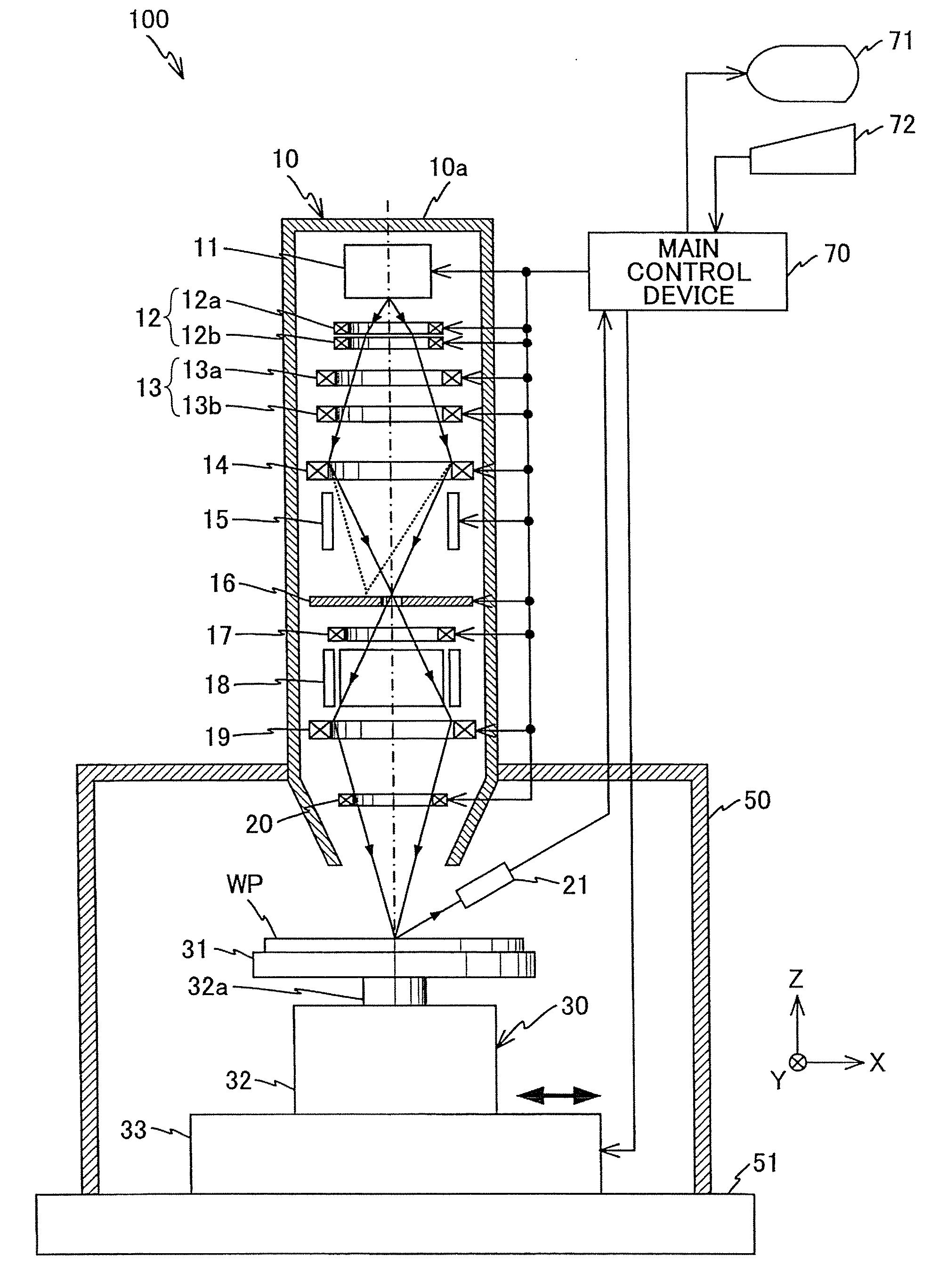
[0106]In the following, a first embodiment of the present invention is described with reference to FIGS. 1 through 9. FIG. 1 is a schematic drawing illustrating a drawing apparatus 100 according to the first embodiment of the present invention. The drawing apparatus 100 is a drawing apparatus capable of drawing a fine pattern on a drawing surface of a sample by irradiating an electron beam onto the sample on which the drawing surface is formed by coating a resist material, for example, under a condition of 10−4 Pa in degree of vacuum.

[0107]As shown in FIG. 1, the drawing apparatus 100 includes a rotary table unit 30 on which a sample is mounted, an irradiation apparatus 10 for irradiating an electron beam onto the sample, a vacuum chamber 50 for housing the rotary table unit 30, and a main control unit 70 for integrally controlling those elements of the drawing apparatus 100.

[0108]The vacuum chamber 50 is a hollow member having a rectangular shape with the bottom (−Z direction) open...

second embodiment

[0141]Next, a second embodiment of the present invention is described with reference to FIGS. 10 through 15. It should be noted that the same reference numerals are used for the same or equivalent elements as those in the first embodiment, and the descriptions of the elements are omitted or abbreviated.

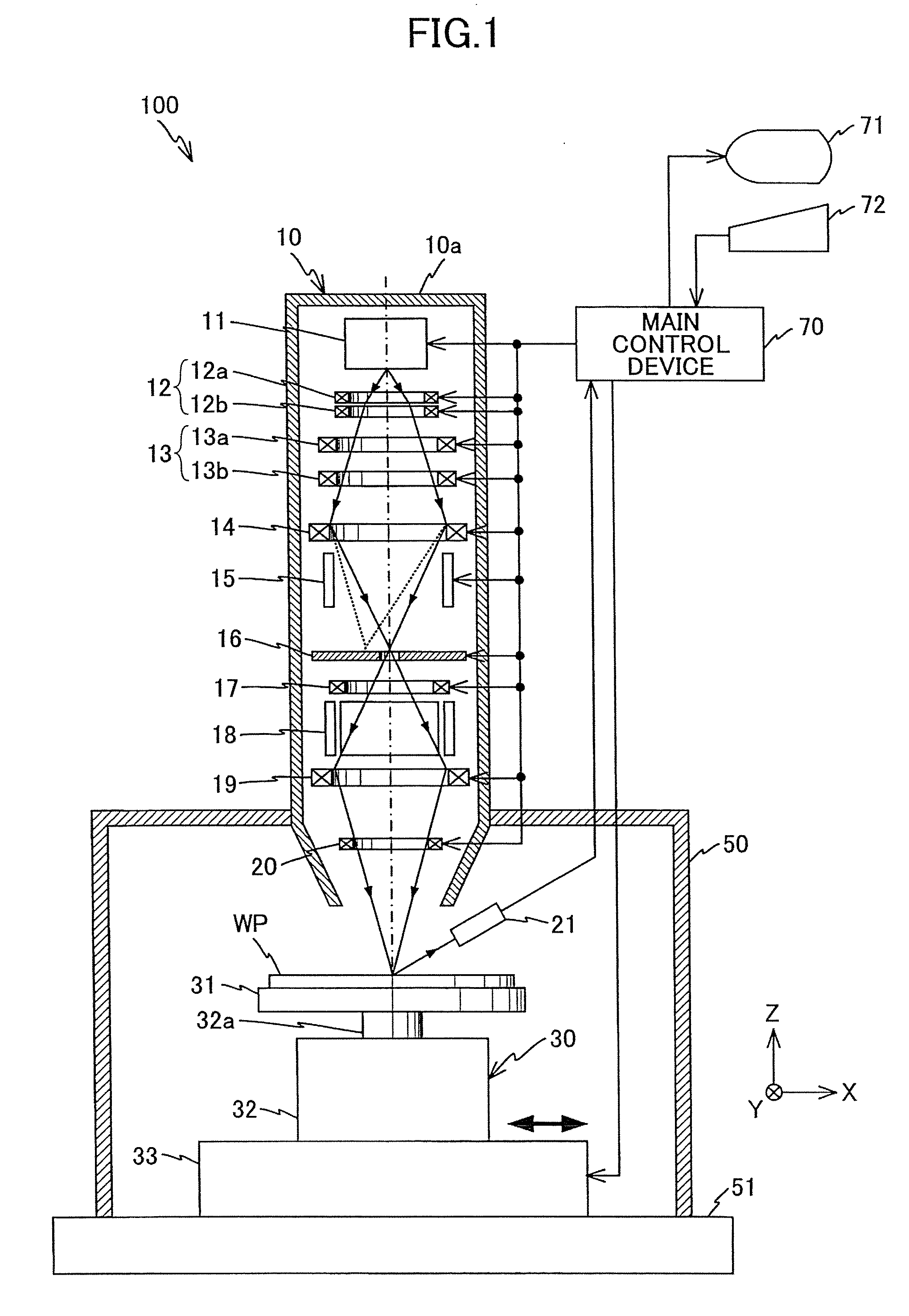
[0142]FIG. 10 is a flowchart showing a series of processes carried out by the main control device 70 in the irradiation apparatus 10 when an astigmatism correction method according to the second embodiment of the present invention is performed. In the following, a method of correcting the astigmatism of the irradiation system in the irradiation apparatus 10 based on the descriptions in FIG. 10 is described. The assumption is that the reference sample “WP” shown in FIG. 11 is mounted on the rotary table 31 of the drawing apparatus 100, an x,y coordinate system with its origin at the center of the reference sample “WP” and an x′,y′ coordinate system rotated 45 degrees with respect to th...

third embodiment

[0161]Next, a third embodiment of the present invention is described with reference to FIGS. 17A through 18B. It should be noted that the same reference numerals are used for the same or equivalent elements as those in the first and second embodiments, and the descriptions of the elements are omitted or abbreviated.

[0162]An aberration correction method according to the third embodiment of the present invention is different from that of the above-mentioned second embodiment in the process of focus adjustment in step 201 in FIG. 10. In the following, the focus adjustment method is described.

[0163]Here, since the positional relationship between the objective lens 19 and the rotary table 31 is constant, a current value supplied from the main control device 70 to the objective lens (herein after referred to as DAC value) when the focusing position of an electron beam that receives refractive power by the objective lens 19 is focused in the vicinity of the upper surface of the rotary tabl...


PUM


Abstract

A method of evaluating astigmatism of an irradiation system irradiating an electron beam is disclosed. In this method, a figure pattern consisting of plural (for example, four) concentric circles is formed on a reference sample “WP” and an image (scanned image) is formed based on an electron signal obtained by scanning the electron beam onto the reference sample “WP”. In the scanned image, the image has a blur in a region with its longitudinal direction parallel to the generating direction of the astigmatism and the size of the blur depends on magnitude of the astigmatism. Therefore, the direction and the magnitude of the astigmatism of the irradiation system of an irradiation apparatus can be detected based on the obtained scanned image.

Description

TECHNICAL FIELD[0001]The present invention relates to an aberration evaluation pattern, an aberration evaluation method, an aberration correction method, an electron beam drawing apparatus, an electron microscope, a master, a stamper, a recording medium, and a structure, and more specifically, to an aberration evaluation pattern evaluating the aberration of an irradiation system scanning a surface of a sample, an aberration evaluation method evaluating the aberration of an irradiation system based on an electronic signal obtained by scanning the aberration evaluation pattern with an electron beam, an aberration correction method correcting the aberration of the irradiation system based on the evaluation result obtained by the aberration evaluation method, an electron beam drawing apparatus having an irradiation system whose aberration is corrected using the aberration correction method, an electron microscope having an irradiation system whose aberration is corrected using the aberr...

Claims


Application Information

Patent Timeline
IPC IPC(8): G11B5/33H01J37/30H01J37/26G01N23/00B32B3/30G06K9/00B32B3/02
CPCH01J37/153H01J37/28Y10T428/24479H01J2237/282H01J2237/1532H01J37/304G03F7/70516H01J37/3174
Inventor MIYATA, HIROYUKIMIYAZAKI, TAKESHIKOBAYASHI, KAZUHIKOHAYASHI, KUNITO
Owner RICOH KK
Why Eureka
Try Eureka