
Biomass fuel burning equipment and burning method thereof

A biomass fuel and combustion equipment technology, applied in combustion methods, combustion equipment, solid fuel combustion and other directions, can solve the problems of inability to centralize cleaning, easy environmental pollution, high maintenance costs, and achieve the effects of convenient cleaning and high combustion efficiency

Active Publication Date: 2014-01-29
泉州超然热能设备发展有限公司
View PDF11 Cites 14 Cited by
  • Summary
  • Abstract
  • Description
  • Claims
  • Application Information

AI Technical Summary

Problems solved by technology

[0004] This kind of rotary air-cooled grate system can make the powder evenly distributed on the grate for combustion to a certain extent, but it has the following disadvantages. First, the ash after the fuel is burned on the grate is not easy to fall, and After that, it falls directly below the grate, so it cannot be cleaned in a centralized manner, and the dust will fly and easily pollute the environment during cleaning; second, the small particles in the fuel are easy to fall directly from the air outlet of the grate without burning, increasing the heat loss of incomplete combustion; First, the periphery of the grate is not easy to seal, resulting in air leakage and affecting combustion efficiency; fourth, the pulley and belt motor are easily deformed after being heated, prone to failure, and high maintenance costs

Method used


Image

  • Biomass fuel burning equipment and burning method thereof
  • Biomass fuel burning equipment and burning method thereof
  • Biomass fuel burning equipment and burning method thereof

Examples


Embodiment Construction

[0025] The present invention will be further described below through specific embodiments.

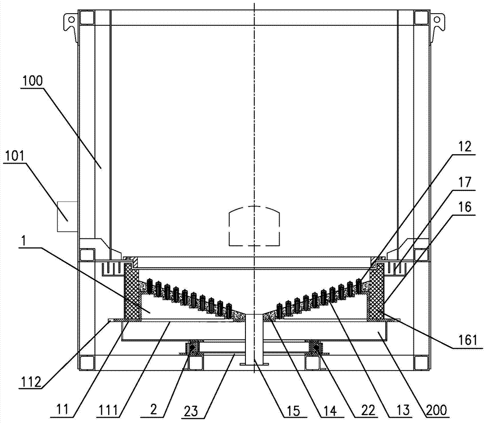
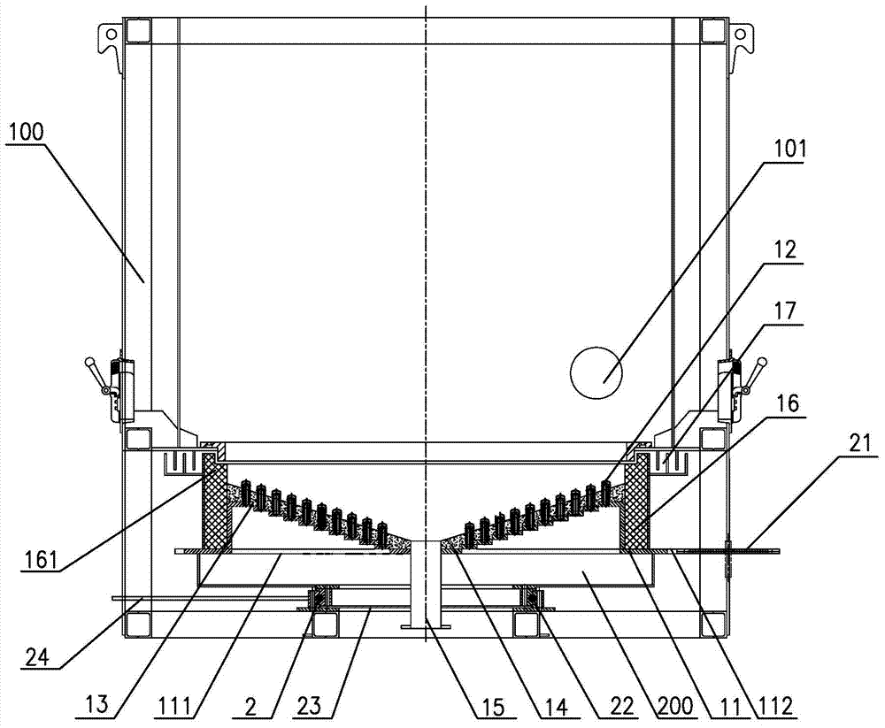
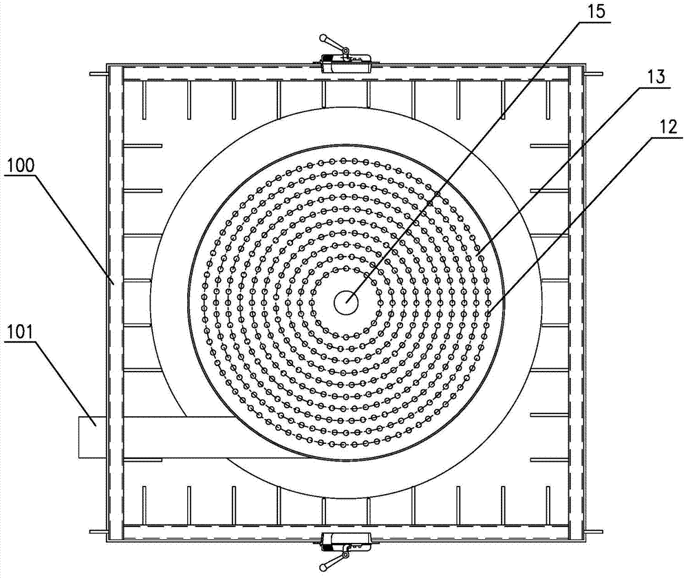
[0026] refer to Figure 1 to Figure 4 As shown, a biomass fuel combustion equipment is suitable for supporting boilers, water heaters and hot blast stoves, etc., including a combustion furnace 100 and an air supply device 200, and the combustion furnace 100 is provided with a rotatable fire grate 1 and the grate rotation driving device 2, the air supply device 200 communicates with the combustion furnace 100 and delivers high-pressure air to the bottom of the grate 1.

[0027] The grate 1 includes a rotating bottom plate 11, a plurality of hoods 12, a hood support plate 13, a refractory mud layer 14, an ash fall pipe 15, a sealing plate 16 and a sealing device 17;

[0028] The rotating bottom plate 11 is a circular structure with an air inlet 111 on its bottom and a ring gear 112 on its outer edge;

[0029] The air cap 12 is a circular tube structure with one end closed, and the tube...


PUM


Abstract

The invention relates to biomass fuel burning equipment and a burning method thereof. The biomass fuel burning equipment comprises a burning furnace and a blowing device, a rotatable fire grate and a fire grate rotation driving device are arranged in the burning furnace, the fire grate comprises a circular bottom rotating plate, a plurality of groups of funnel caps, fireproof clay layers, an ash pipe and a sealing plate, wherein the funnel caps are arranged above the bottom rotating plate, the fireproof clay layers are paved on the funnel caps, the ash pipe is connected to the circular center of the bottom rotating plate, and the sealing plate is fixed at the outer edge of the bottom rotating plate. The biomass fuel burning equipment and the burning method thereof are applicable to assorted boilers, water heaters, air heaters and the like, and are used for burning biomass energy, fuel is uniformly arranged and suspended on the fire grate to burn after entering the burning furnace, and burning efficiency is high. Ash after power burning can be discharged completely from the ash pipe, an air inlet system is prevented from being blocked by the ash during burning, and the ash is collected and recycled, is convenient to clean and free of affection on the environment.

Description

technical field [0001] The invention relates to the technical field of combustion stoves, in particular to a combustion device for burning biomass fuels such as sawdust, straw, chaff, palm fruit bunches, agricultural and forestry waste, and a combustion method for the device. Background technique [0002] The grate is a part of the combustion equipment used to pile up fuel and make it burn effectively. The traditional grate carries block fuel, and there are usually strip grilles on the grate to facilitate the discharge of cinders and provide fuel for combustion. Oxygen, the traditional grate cannot carry powdered fuel or biomass energy, and it is easy to cause problems such as ash clogging and poor oxygen supply. [0003] In order to solve the above problems, the Chinese invention patent application (application number: 201210342648.8) discloses a new type of biomass filtration rotary air-cooled grate system, including a rotating shaft, a grate chassis, a chassis bracket, a ...

Claims


Application Information

Patent Timeline
IPC IPC(8): F23B30/04F23H9/00
Inventor 黄迁建
Owner 泉州超然热能设备发展有限公司
Learn More