
Air purifying device

An air purification device and filter technology, applied in the field of air purification, can solve the problems of limited ability to deal with air pollution, limited range of treatment space, low output ion concentration, etc., to achieve large action space, long life, and high ion concentration Effect

Active Publication Date: 2014-01-29
王大君
View PDF3 Cites 8 Cited by
  • Summary
  • Abstract
  • Description
  • Claims
  • Application Information

AI Technical Summary

Problems solved by technology

In order to improve ambient air quality, create a clean and suitable environment, and protect human health, various air purification products have appeared on the market, but the ability to deal with air pollution is limited, the output ion concentration is very low, and the range of treatment space is limited.
[0003] Generally, air purifiers use filters or combined filters to filter and eliminate floating dust without exception. This requires a fan to suck air into the air purifier, and then filter all kinds of floating dust on the filter in the machine. In this way, The efficiency is very low, and the filter screen will be polluted quickly and needs to be replaced. However, the general filter screen cannot do anything about the particles within PM2.5

Method used


Image

  • Air purifying device
  • Air purifying device
  • Air purifying device

Examples


Embodiment 1

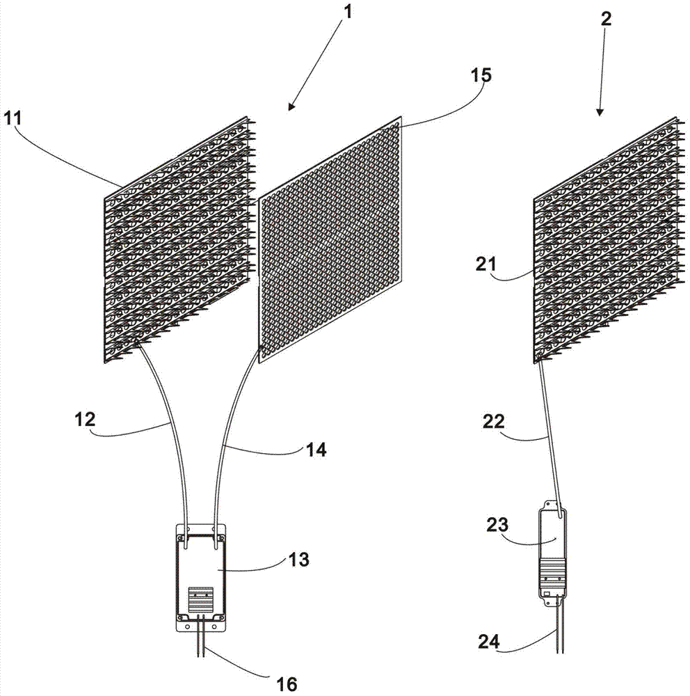
[0039] see figure 1 The shown air cleaning device comprises an electronic filter screen assembly 1 and an anion generator assembly 2, and a first distance is provided between the electronic filter screen assembly 1 and the anion generator assembly 2, wherein,

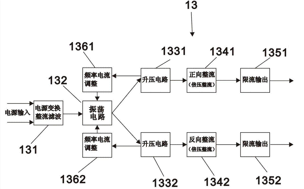
[0040] The electronic filter assembly 1 comprises a first negative ion emission plate 11, a first negative ion emission line 12, a positive and negative high voltage module 13, a positive high voltage line 14 and an electronic filter screen 15; the positive and negative high voltage module 13 passes through the first negative ion emission line 12 is connected with the first negative ion emission plate 11, and is connected with the electronic filter screen 15 by positive high voltage line 14; The second spacing is provided between the first negative ion emission plate 11 and the electronic filter screen 15, and relative arrangement;

[0041] Described negative ion generator assembly 2 comprises the second negative ion em...

Embodiment 2

[0055] Referring to Example 1, this example includes all the contents of Example 1, but unlike Example 1, in order to increase the ability to remove particles within PM2.5, see Figure 5 , the electronic filter assembly 1 also includes a third negative ion emission plate 17, the third negative ion emission plate 17 is located on the other side of the electronic filter screen 15 relative to the first negative ion emission plate 11, between it and the electronic filter screen 15 There is a third distance between them, which is also set relatively. The relative setting here also means that the negative ion emitting end of the third negative ion emitting plate 17 points to the electronic filter screen 15 . In order to enable the third anion emission board to work, it can be connected to the positive and negative high voltage modules (not shown) through a third anion emission line accordingly; a third anion generator 19 can also be provided separately, and then the third anion Gen...

Embodiment 3

[0057] With reference to embodiment 1, this embodiment includes the whole content of embodiment 1, but different from embodiment 1, see Figure 6 , in order to use more conveniently and safely, the air cleaning device of the present embodiment is provided with a casing 3, is provided with electronic filter screen assembly 1 and negative ion generator assembly 2 then in casing 3, and electronic filter screen assembly 1 and negative ion generator assembly 2 A fan 4 is arranged between the generator components 2 . The function of the fan 4 is to enable the air purification device to form a wind flow. Therefore, an air duct 5 (the number shown in the figure is only a part of the air duct) is provided in the housing. The air duct 5 has an air inlet 6 and an air outlet. 7. The air inlet 7 leads to the first anion emitting board 11 , while the second anion emitting board 21 points to the air outlet 7 . The first anion emitting plate 11 and the second anion emitting plate 21 are all ...


PUM


Abstract

The invention discloses an air purifying device which comprises an electronic filter screen component and a negative ion generator component. A first gap is formed between the electronic filter screen component and the negative ion generator component. The electronic filter screen component comprises a first negative ion transmitting board, a first negative ion transmitting line, a positive-negative high voltage module, a positive high voltage line and an electronic filter screen, wherein the positive-negative high voltage module is connected with the first negative ion transmitting board through the first negative ion transmitting line and connected with the electronic filter screen through the positive high voltage line, and a second gap is formed between the first negative ion transmitting board and the electronic filter screen which are opposite. The negative ion generator component comprises a second negative ion transmitting board, a second negative ion transmitting line and a negative ion generator, wherein the negative ion generator is connected with the second negative ion transmitting board through the second negative ion transmitting line, and the second negative ion transmitting board and the first negative ion transmitting board are disposed in the same direction. The air purifying device is capable of outputting high-concentration negative oxygen ions and effectively eliminating floating dust, especially particles within PM2.5 (particulate matter2.5).

Description

technical field [0001] The invention relates to the field of air purification, in particular to an air purification device. Background technique [0002] With the continuous development of industry and transportation, a large amount of harmful substances are discharged into the air, which changes the normal composition of the air and deteriorates the air quality. When we live in polluted air, our health suffers. In order to improve ambient air quality, create a clean and suitable environment, and protect human health, various air purification products have appeared on the market, but their ability to deal with air pollution is limited, the output ion concentration is very low, and the range of treatment space is limited. [0003] Generally, air purifiers use filters or combined filters to filter and eliminate floating dust without exception. This requires a fan to suck air into the air purifier, and then filter all kinds of floating dust on the filter in the machine. In thi...

Claims


Application Information

Patent Timeline
Patent Type & Authority Applications(China)
IPC IPC(8): F24F1/00F24F13/28B03C3/017B01D53/74B01D53/72
Inventor 王大君
Owner 王大君
Learn More