
A thermal protection method for a launch pad

A launch pad and thermal protection technology, which is applied to rocket launchers, offensive equipment, weapon types, etc., can solve problems such as inconvenient maintenance, poor craftsmanship of launch pads, and uncontrollable costs, so as to save costs, improve the working environment, Suppresses the effect of area of ​​influence

Active Publication Date: 2015-09-16
BEIJING INST OF SPACE LAUNCH TECH +1
View PDF5 Cites 0 Cited by
  • Summary
  • Abstract
  • Description
  • Claims
  • Application Information

AI Technical Summary

Problems solved by technology

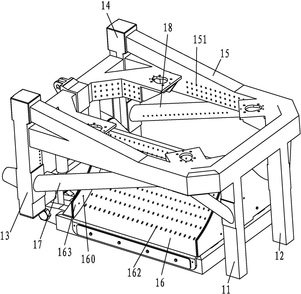
[0003] At present, the thermal protection technology adopted by the launch pad is mainly based on two directions. One is to adopt a reasonable flow diversion method to avoid or reduce the influence of the launch pad and rocket launch vehicle support structure from the exhaust gas flow. Currently, optimized double-sided and single-sided The diversion surface, in the launching position where the range of gas exhaust is strictly limited for mobile launch, these optimized double-sided and single-sided diversion surfaces cannot meet the requirements of use; the second is to use reasonable thermal protection materials, and use thermal protection materials to resist high The ablation damage effect of hot gas flow delays the transfer process of high heat flow to the launch platform structure. Now the main use is adiabatic composite materials or coatings, but adiabatic composite materials or coatings have limited anti-ablation life and their repairability It has also become a big problem in the maintenance work of the launch pad
[0004] The above thermal protection methods are all passive thermal protection, resulting in many problems such as poor manufacturability of the launch pad, uncontrollable cost, and inconvenient maintenance.

Method used


Image

  • A thermal protection method for a launch pad
  • A thermal protection method for a launch pad
  • A thermal protection method for a launch pad

Examples


Embodiment Construction

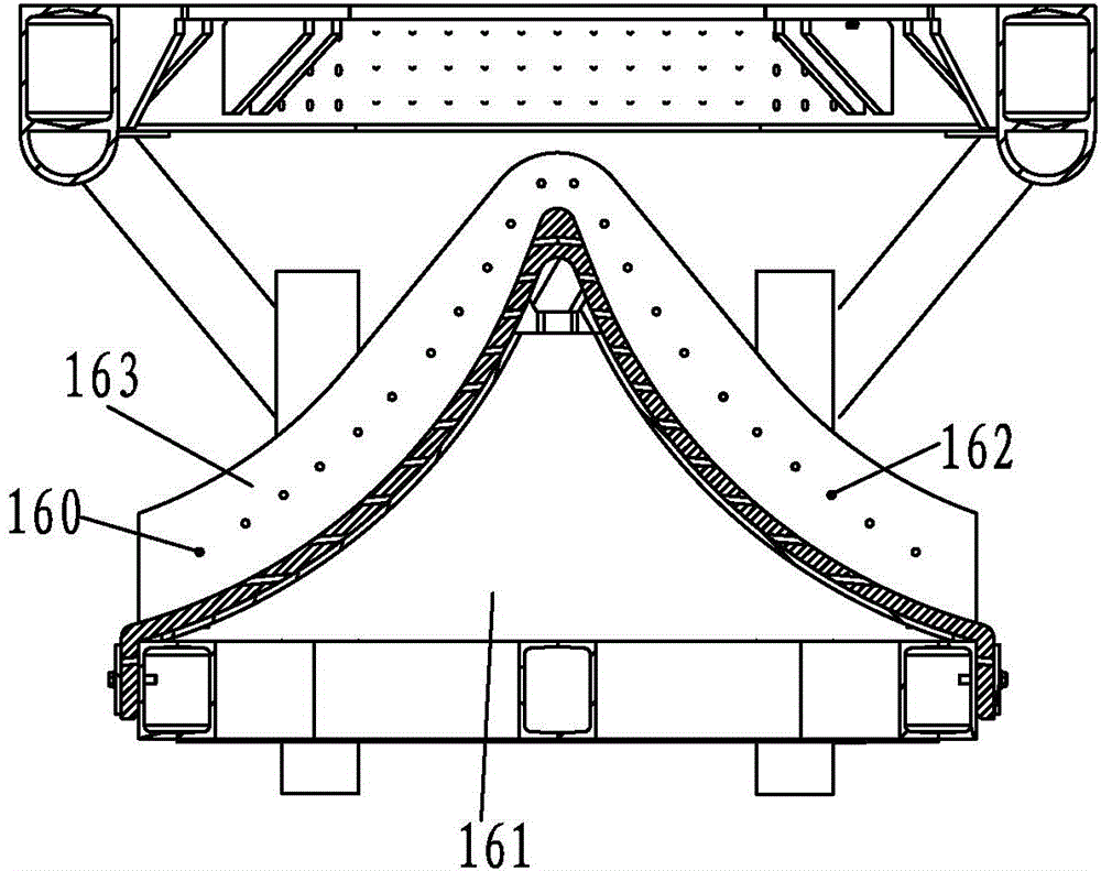
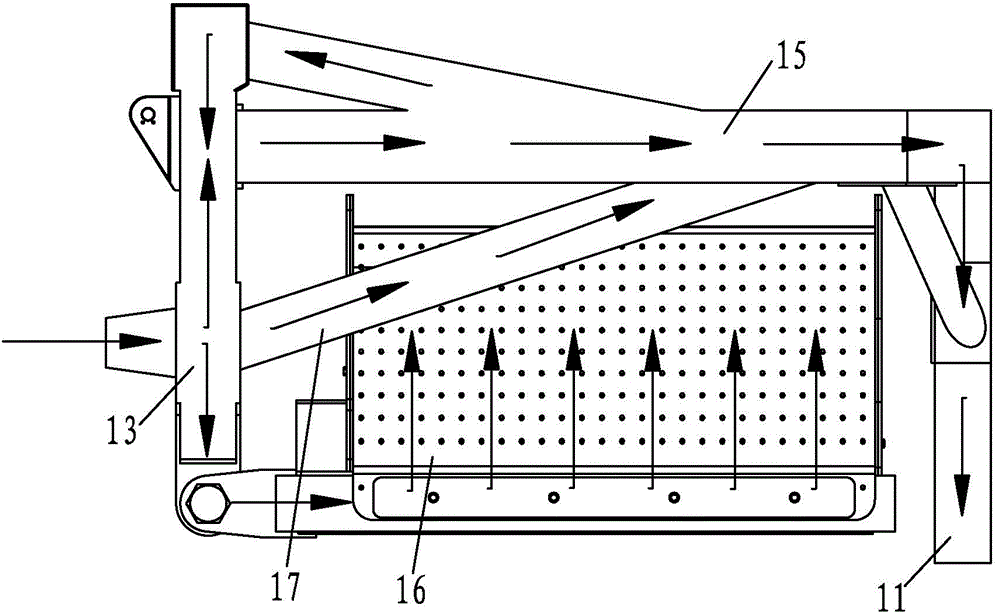
[0014] like figure 1 As shown, the water spray cooling type launching platform of the present invention comprises outer front and rear support columns 11,12, inner front and rear support columns 13,14, support ring frame 15, diversion cone 16, and support ring frame 15 is fixed on each support At the top of the column, the diversion cone 16 is fixed on the inner side of the bottom of each support column. Between the support ring frame 15 and the inner front and rear support columns 13, 14, there are respectively front and rear oblique supports 17, 18, and the outer front and rear support columns 11 and 12, the inner front and rear support columns 13 and 14, the support ring frame 15 and the front and rear oblique supports 17 and 18 are all hollow structures, and each hollow part forms each support column, support ring frame 15 and front and rear oblique supports respectively. Support the main water channel for water spraying on the support 17,18, the outer front and rear suppo...


PUM


Abstract

The invention discloses a thermal protection method for a launch pad. The thermal protection method is characterized in that water spray main channels are arranged on components of the launch pad, water nozzles are formed in the various water spray main channels, cooling water sources are connected with the various water spray main channels, cooling water is sprayed out of the various water nozzles after a rocket is ignited, is sprayed on flame of a nozzle of an engine of the rocket and is preliminarily mixed with high-temperature gas flow sprayed out of the nozzle of the engine to form cooling water mist, and momentum and heat are exchanged between the high-temperature and high-speed gas flow and water flow sprayed out of the water nozzles in the procedure, so that the temperature of the gas flow sprayed on the launch pad can be reduced. The thermal protection method has the advantages that the intensity of ablation of the gas spray flow to launch equipment in a rocket launch procedure can be effectively reduced, and the cost is low.

Description

technical field [0001] The invention relates to a cooling method, in particular to a heat protection method for a launch pad. Background technique [0002] During the maneuvering launch of weapons, the high-temperature, high-speed, and highly condensed-phase gas flow will firstly ablate the launch pad, especially the flow guide device of the launch pad. The ablation and damage effect of the gas flow on the launch pad is mainly through the high-speed, high-temperature air flow that quickly transmits a large flow of heat into the launch pad structure, and the heat flux density transmitted from the surface of the launch pad structure to the interior reaches tens of megawatts per unit area or even above As a result, the key structures of the launch pad will heat up rapidly and the structural strength will be greatly reduced. How to thermally protect the key structures of the launch pad and avoid serious damage to the launch pad structure or even collapse has become a concern of ...

Claims


Application Information

Patent Timeline
Patent Type & Authority Patents(China)
IPC IPC(8): F41F3/04
Inventor 陈劲松吕永志董小伟刘奇王明华张博宇
Owner BEIJING INST OF SPACE LAUNCH TECH
Learn More