Steel plate oddment monitoring method and system

A monitoring system and surplus material technology, applied in the direction of comprehensive factory control, electrical program control, comprehensive factory control, etc., can solve the problems of high cost of steel plate surplus material, waste of raw materials, difficult to find surplus material, etc., to improve the utilization rate of materials, The effect of reducing production cost and improving competitive advantage

Inactive Publication Date: 2014-01-29
HUAZHONG UNIV OF SCI & TECH
5 Cites 10 Cited by

AI-Extracted Technical Summary

Problems solved by technology

At present, in the field of sheet metal cutting and processing, some steel plate surplus materials are wasted because they have not been reused because the information of these surplus materials has not been filed.
In addition, some remaining steel plates are laid out again during layout, but it is difficult to find the remaining material when cutting, or the cost of using the remaining ...

Method used

As shown in Figure 3, in the process of embedding RFID5, a through hole with a diameter of 18mm is cut at the edge corner of the remaining material to be monit...

Abstract

The invention discloses a steel plate oddment monitoring method which is applied in a steel plate oddment monitoring system. The method includes that a server receives layout results from a layout system and determines whether the layout results contain oddment information; if so, a cutting site management terminal acquires the layout results from the server according to production plan, an operator prepares material according to plate blank information, a numerical-control cutting platform cuts the prepared plate blanks according to a numerical-control program and layout images, the cutting site management terminal sends oddment information to a RFID reader after cutting of the numerical-control cutting platform is completed, the RFID reader writes the oddment information into a RFID and embeds the RFID into the oddment, and the operator stores the oddment with the embedded RFID into a plate blank bin and sends storing position of the oddment to the server through a management terminal of the plate blank bin. By the aid of the method, steel plate oddment monitoring and management can be realized effectively, relevant enterprises can utilize raw material effectively, material utilization can be improved, and production cost can be reduced.

Application Domain

Technology Topic

Image

  • Steel plate oddment monitoring method and system
  • Steel plate oddment monitoring method and system
  • Steel plate oddment monitoring method and system

Examples

  • Experimental program(1)

Example Embodiment

[0027] In order to make the objectives, technical solutions and advantages of the present invention clearer, the following further describes the present invention in detail with reference to the accompanying drawings and embodiments. It should be understood that the specific embodiments described herein are only used to explain the present invention, but not to limit the present invention. In addition, the technical features involved in the various embodiments of the present invention described below can be combined with each other as long as they do not conflict with each other.
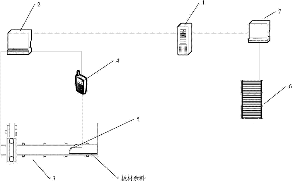
[0028] Such as Figure 4 As shown, the steel plate residual material monitoring method of the present invention is applied in a steel plate residual material monitoring system, which includes a server, a cutting site management terminal, a numerical control cutting platform, an RFID reader, RFID, and a plate library. It includes the following steps:
[0029] (1) The server receives the layout result from the sampling system, and judges whether the layout result includes residual material information, if it does, go to step (2), otherwise the process ends; the layout result also includes plate information, NC program and Layout drawing, the remaining material information includes the shape, material and thickness of the remaining material;
[0030] (2) The cutting site management terminal obtains the layout results from the server according to the production plan;
[0031] (3) The operator prepares materials according to the sheet information (mainly the shape, material, thickness and storage location of the sheet);
[0032] (4) The CNC cutting platform cuts the prepared plates according to the NC program and layout drawing;
[0033] (5) The cutting site management terminal will send the remaining material information to the RFID reader after the cutting of the CNC cutting platform is completed;
[0034] (6) The RFID reader writes the remaining material information into the RFID, and embeds the RFID in the remaining material;
[0035] (7) The operator stores the remaining material embedded in the RFID into the plate library, and sends the storage location of the remaining material to the server through the management terminal of the plate library.
[0036] Such as figure 1 As shown, the steel plate residual material monitoring system of the present invention includes a server 1, a cutting site management terminal 2, a numerical control cutting platform 3, an RFID reader 4, an RFID5, a plate library 6 and a plate library management terminal 7, and a cutting field management terminal 2. The management terminal of the board library 6 is connected to the server 1, the cutting site management terminal 2 is connected to the numerical control cutting platform 3, and the RFID reader 4 communicates with the cutting site management terminal 2 and the board library management terminal 7 through the network. In this embodiment, the network may be a WiFi network.
[0037] The server 1 is used to receive the layout result from the sampling system and determine whether the layout result includes residual material information. The layout result also includes sheet information, NC program and layout drawing, and the remaining material information includes the shape, material and thickness of the remaining material.
[0038] The cutting site management terminal 2 is used by the server 1 to obtain the layout result from the server 1 according to the production plan when the server 1 judges that the layout result includes residual material information.
[0039] The numerical control cutting platform 3 is used for cutting the plates prepared according to the plate information according to the NC program and the layout drawing.
[0040] The cutting site management terminal 2 is also used to send the remaining material information to the RFID reader 4 after the cutting of the CNC cutting platform 3 is completed.
[0041] The RFID reader 4 is used to write the remaining material information into the RFID5 and embed the RFID5 in the remaining material. Such as figure 2 As shown, RFID5 adopts high temperature resistant and metal resistant electronic tags and can be reused to record the shape, size, material, thickness, storage location, generation time and other information of the remaining steel material.
[0042] Such as image 3 As shown, in the process of embedding the RFID5, a through hole with a diameter of 18mm is cut at the corners of the remaining material to be monitored, and the RFID5 is placed in the through hole, and the remaining material is fixed by interference fit. RFID5 is not easy to fall off.
[0043] The board library 6 is used to store the remaining material after the RFID 5 is embedded, and the storage location of the remaining material is sent to the server 1 through the board library management terminal 7.
[0044] Those skilled in the art can easily understand that the above descriptions are only preferred embodiments of the present invention and are not intended to limit the present invention. Any modification, equivalent replacement and improvement, etc. made within the spirit and principle of the present invention, All should be included in the protection scope of the present invention.

PUM

no PUM

Description & Claims & Application Information

We can also present the details of the Description, Claims and Application information to help users get a comprehensive understanding of the technical details of the patent, such as background art, summary of invention, brief description of drawings, description of embodiments, and other original content. On the other hand, users can also determine the specific scope of protection of the technology through the list of claims; as well as understand the changes in the life cycle of the technology with the presentation of the patent timeline. Login to view more.

Similar technology patents

Classification and recommendation of technical efficacy words

  • Strong reliability
  • High material utilization

Method for monitoring driving state of based on vehicle road cooperation technology

ActiveCN108615364AStrong reliabilityGuaranteed real-time and reliabilityParticular environment based servicesDetection of traffic movementEngineeringSatellite positioning
Owner:RES INST OF HIGHWAY MINIST OF TRANSPORT

Portable type moving lamp

InactiveCN101761782AGuaranteed flameproof performanceStrong reliabilityLighting applicationsProtective devices for lightingBattery holderFront cover
Owner:OCEANS KING LIGHTING SCI&TECH CO LTD +1

Method and apparatus application of metallic alloy coatings

ActiveUS20050000444A1High material utilizationEfficiently coatSpark gapsElectric discharge heatingBond coatingHigh rate
Owner:UNIV OF VIRGINIA
Why Eureka
Try Eureka