Continuous phase QPSK (quadri phase shift keying) modulation method and modulation device for implementing same

A phase control word and phase technology, applied in the field of modulation, can solve the problems of sudden phase change, low complexity, and high complexity of CPM modulation, and achieve the effects of low cost, low complexity and simple structure

Active Publication Date: 2014-01-29
UNIV OF ELECTRONIC SCI & TECH OF CHINA
View PDF4 Cites 4 Cited by
  • Summary
  • Abstract
  • Description
  • Claims
  • Application Information

AI Technical Summary

Problems solved by technology

[0005] The object of the present invention is to overcome the problem of the phase mutation that exists in the PSK modulation mode existing in the prior art and the relatively high deficiency that the CPM modulation mode realizes complexity, provide a kind of continuous phase QPSK modulatio

Method used


Image

  • Continuous phase QPSK (quadri phase shift keying) modulation method and modulation device for implementing same
  • Continuous phase QPSK (quadri phase shift keying) modulation method and modulation device for implementing same
  • Continuous phase QPSK (quadri phase shift keying) modulation method and modulation device for implementing same

Examples


Embodiment 1

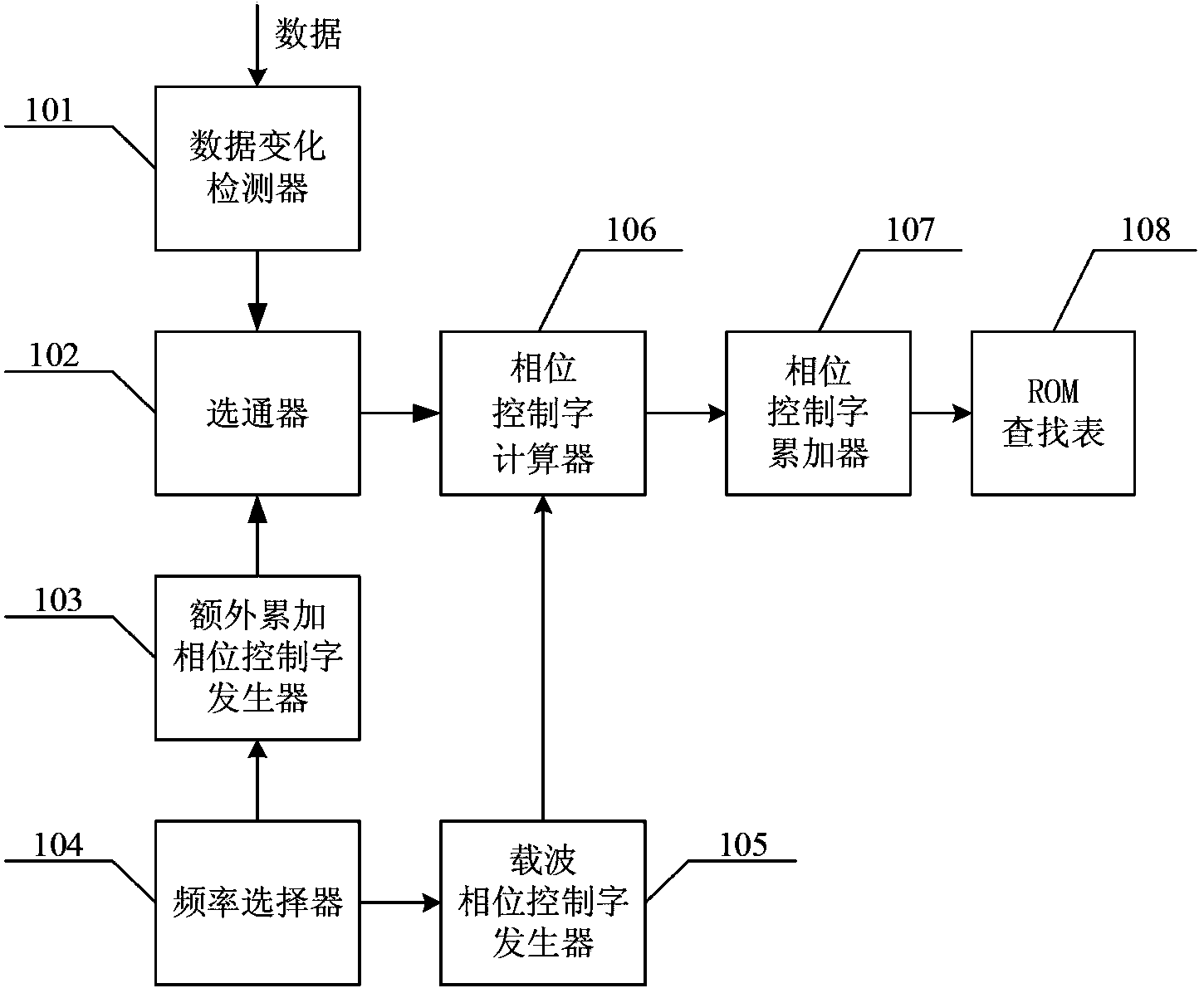
[0049] Such as figure 1 As shown, the continuous phase QPSK modulation device of the present invention includes a data change detector 101, a frequency selector 104, a carrier phase control word generator 105, an additional accumulation phase control word generator 103, a gate 102, and a phase control word calculator 106 , phase control word accumulator 107 and ROM look-up table 108, wherein,

[0050] The data change detector 101 is used to detect whether the data sent by the current clock is the same as the data sent by the adjacent previous clock, and if the data change detector detects that the data sent by the current clock is the same as the data sent by the adjacent previous clock, then output Signal "00", if the sent data is different, different signals will be output according to the phase difference between adjacent sent data waveforms: if the phase difference is π / 2 or -3π / 2, the output signal "01"; if the phase difference is If it is ±π, the output signal is "10"; ...

Embodiment 2

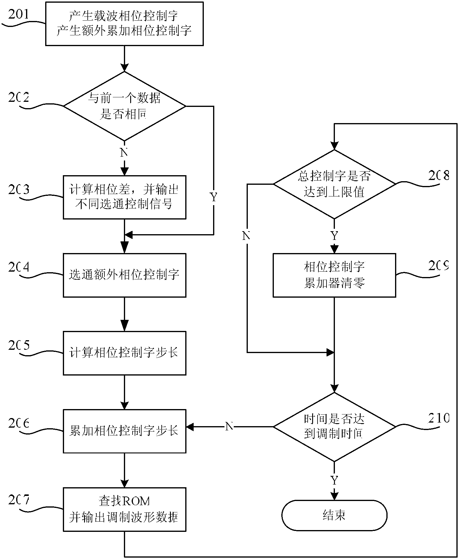
[0059] It should be noted that K represents the depth of the ROM lookup table, that is, the upper limit value of the address of the ROM lookup table. In this embodiment, the value of K is 128.

[0060] It should be noted that, in this embodiment, M represents the length of the excessive waveform, that is, after M clock cycles, the additional accumulated phase reaches the phase difference value, specifically:

[0061] When the phase difference is π / 2 or -3π / 2, the first additional accumulated phase reaches π / 2 after M clock cycles, and the transition waveform is smoothly connected with the modulation waveform of the current data;

[0062] When the phase difference is ±π, the second additional accumulated phase reaches π after M clock cycles, and the transition waveform is smoothly connected with the modulation waveform of the current data;

[0063] When the phase difference is 3π / 2 or -π / 2, the third additional accumulated phase reaches 3π / 2 after M clock cycles, and the transi...


PUM


Abstract

The invention discloses a continuous phase QPSK (quadri phase shift keying) modulation device which comprises a data change detector, a frequency selector, a carrier phase control word generator, an extra accumulation phase control word generator, a gate, a phase control word calculator, a phase control word accumulator and an ROM (read only memory) lookup table. The invention further discloses a continuous phase QPSK modulation method. The continuous phase QPSK modulation device and the continuous phase QPSK modulation method have the advantages that the modulation device is simple in structure and easy to implement; by the continuous phase QPSK modulation method, a continuous phase transitional waveform of a prior data waveform is smoothly transited to a modulation waveform of current data, so that the modulation waveform is continuous, phase jump in modulation waveforms in transmitting data of a former adjacent clock and a later adjacent clock can be eliminated, accordingly, pulse response caused by sudden change of phases can be eliminated, symbol rate information contained in waveform signals can be concealed, and the communication safety and the communication confidentiality can be improved.

Description

technical field [0001] The present invention relates to a modulation method, in particular to a continuous phase quadrature phase shift keying (Quadrature Phase Shift Keying, QPSK for short) modulation method. Background technique [0002] Phase Shift Keying (PSK for short) is a modulation technique that uses carrier phase to represent input signal information, that is, uses phase changes to transmit digital information. Binary Phase Shift Keying (BPSK for short), Quadri Phase Shift Keying (QPSK for short) and offset quadrature phase shift keying used in IS-95 and IMT-2000 Offset QPSK (OQPSK for short) and so on belong to the phase shift keying modulation method. [0003] When using phase shift keying technology for signal modulation, the phase change is sudden. In QPSK, the transmitted carrier signal has 4 possible phase values, which can be expressed as θ 0 +l·π / 2, where θ 0 is the initial phase value, and l=0,1,2,3. Therefore, when the transmitted data changes, the c...

Claims


Application Information

Patent Timeline
IPC IPC(8): H04L27/20
Inventor 吴廷勇朱文翰周将运胡剑浩李少谦
Owner UNIV OF ELECTRONIC SCI & TECH OF CHINA
Why Eureka
Try Eureka