Current collecting piece welding device, lower current collecting piece welding device and fixture of lower current collecting piece welding device

A current collector and fixture technology, applied in the field of supercapacitor current collector welding fixtures, can solve problems such as poor positioning accuracy, eccentricity between winding core and current collector, and unstable assembly quality, saving man-hours and costs, improving Work efficiency, the effect of improving work efficiency

Active Publication Date: 2014-02-05
TIG TECH CO LTD
View PDF7 Cites 9 Cited by
  • Summary
  • Abstract
  • Description
  • Claims
  • Application Information

AI Technical Summary

Problems solved by technology

If the positioning accuracy is poor, the assembly quality will be unstable; if the structure of the fixture is unreasonable, it will affect the electrical conductivity and welding strength of the winding core to varying degrees during assembly.
[0004] In the prior art, there is a tooling fixture with a three-jaw structure, which shrinks and clamps the winding core by shrinking the three-jaw fixing ring and makes close contact with the current collector. However, since the three claws move and clamp the winding core at the same time, friction between each other, the eccentricity of the winding core and the current collector often occurs during use, which cannot meet the production process requirements
In addition, the fixture cannot meet the needs of welding cores and current collectors of different heights.

Method used


Image

  • Current collecting piece welding device, lower current collecting piece welding device and fixture of lower current collecting piece welding device
  • Current collecting piece welding device, lower current collecting piece welding device and fixture of lower current collecting piece welding device
  • Current collecting piece welding device, lower current collecting piece welding device and fixture of lower current collecting piece welding device

Examples


Embodiment 1

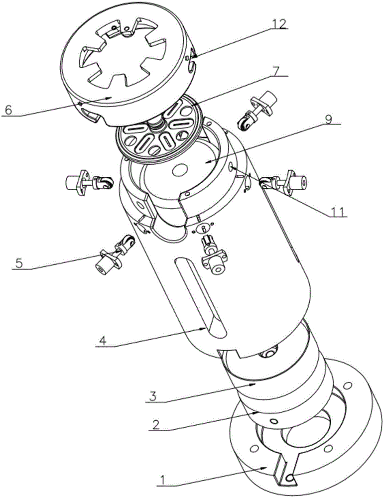
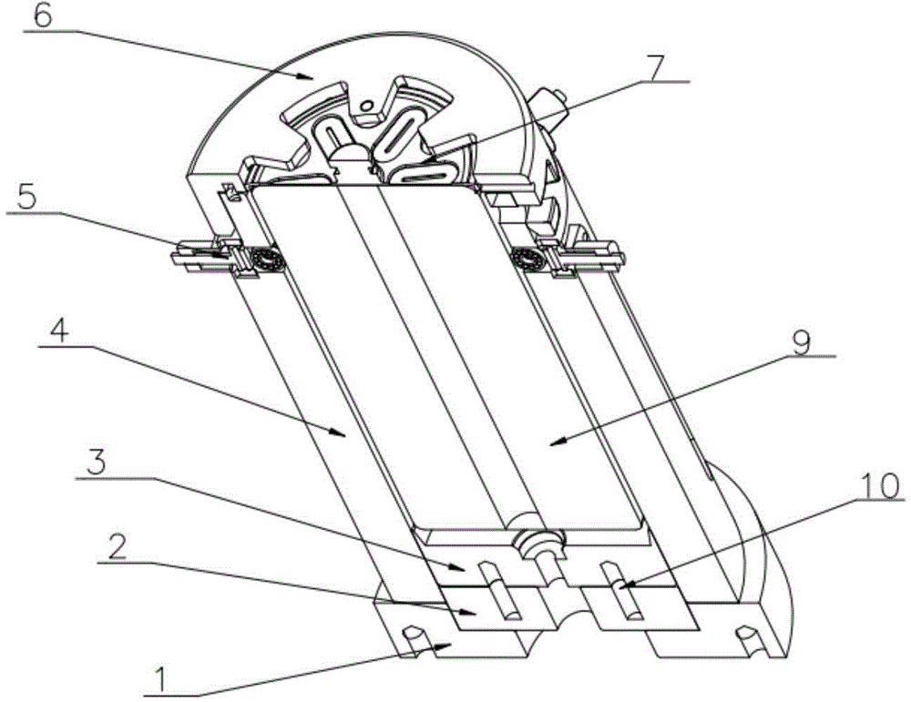
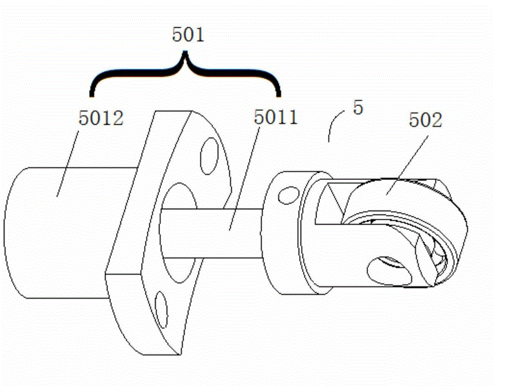
[0031] Such as figure 1 , figure 2 As shown, the lower current collector welding jig of this embodiment includes a base 1, a guide block 2, a winding core support block 3, a jig body 4 and an upper cover 6; the base 1, the guide block 2 and the winding core The supporting blocks 3 are arranged sequentially from bottom to top, and the center of the winding core supporting block 3 is provided with a centering groove 301, and the centering groove 301 is used to center one end of the winding core 9 of the supercapacitor to be processed. position; the clamp cylinder 4 is connected to the base 1, and is covered outside the guide block 2 and the winding core support block 3; the clamp cylinder 4 is set at a certain height from the base 1 The centering part 5 is used to apply pressure to the winding core 9 of the supercapacitor to be processed so that it is in the center position; the bottom wall of the upper cover 6 has a working window required for laser welding, and the side wall...

Embodiment 2

[0040] The lower current collector welding device of this embodiment includes a power component, a rotating support platform, two or more jigs for welding the lower current collector as described in Embodiment 1, and two or more laser welding parts correspondingly arranged, each The lower current collector welding jig is evenly arranged on the rotating support platform along the circumferential direction, and the guide block can drive the core support block to move under the action of the power component, so that the lower current collector It is close to the winding core of the supercapacitor to be processed. This design can have multiple welding stations, which can simultaneously weld the lower current collectors of multiple products, thereby improving efficiency.

[0041] The above-mentioned rotating support platform can also be a mobile support platform, as long as the conversion between the two stations of product loading and unloading and product welding can be realized....

Embodiment 3

[0043] The current collector piece welding device of this embodiment includes a rotating support platform, a jig for upper current collector piece welding, the lower current collector piece welding device described in Embodiment 2, and correspondingly arranged laser welding components. The jig for welding the upper current collector and the jig for welding the lower current collector are symmetrically arranged on the rotating support platform.

[0044] Such as Figure 4 and Figure 5 As shown, the clamp for welding the upper current collector includes a second base 1′, a second guide block 2′, a second winding core support block 3′, a second clamp cylinder 4′ and a second upper cover 6′, the second The clamp cylinder 4' is set on the second base 1', the second guide block 2' and the second winding core support block 3' are inside the second clamp cylinder 4'; the bottom of the second upper cover 6' The wall is provided with a second working window required for laser welding,...


PUM


Abstract

The invention provides a current collecting piece welding device, a lower current collecting piece welding device and a fixture of the lower current collecting piece welding device. The fixture comprises a base, a guide block, a winding core support block, a fixture barrel and an upper cover; a centering groove and a through hole are formed in the center of the support block; the fixture barrel is arranged outside the guide block and the winding core support block in a covering manner; the fixture barrel is provided with centering parts; a through hole needed for laser welding is formed in the bottom wall of the upper cover, and fastener grooves are formed in the side wall; bosses are arranged on the peripheral well of the fixture clamp. The fixture has the advantages that since the support block with the center provided with the centering groove and the fixture barrel provided with the centering parts are arranged at two ends of a winding core of a supercapacitor to be processed respectively, the winding core of the supercapacitor to be processed can be positioned from the upper and lower portions accurately; meanwhile, by the aid of the support block, the fixture is suitable for welding of supercapacitor winding cores and current collecting pieces with different heights and convenient for changing the line of production, and labor-hour and cost are saved.

Description

technical field [0001] The invention relates to a fixture, in particular to a fixture used for welding supercapacitor current collectors. Background technique [0002] In the production process of welded supercapacitors, there is usually a process of welding the upper and lower current collectors with the winding core by laser welding, and leading out the positive and negative poles of the winding core, which has good electrical conductivity and welding strength. , this process is crucial to the quality of the product. [0003] For laser welding, the positioning accuracy of the welding position of the supercapacitor winding core is the most basic factor affecting its assembly quality. Most of the positioning methods in the prior art use fixtures to position the welding position. Then, whether the design of the fixture is reasonable or not has a great influence on the quality of electronic components. If the positioning accuracy is poor, the assembly quality will be unstabl...

Claims


Application Information

Patent Timeline
Patent Type & Authority Applications(China)
IPC IPC(8): B23K37/04B23K26/21B23K26/70
CPCB23K26/0823B23K26/20B23K26/702B23K2101/36
Inventor 刘海湘倪杰廖运平
Owner TIG TECH CO LTD
Why Eureka
Try Eureka