
EOD (Explosive Ordnance Disposal) robot control system, EOD robot control method and EOD robot using EOD robot control method

It is a technology for EOD robots and control systems. It is applied in the direction of program control manipulators, manipulators, and manufacturing tools. It can solve the problems of unbalanced layout, inability to adapt to complex terrain, and inability to complete tasks. It achieves a moderate wireless radio frequency transmission distance and is easy to automate. Control and reduce the effect of workload

Active Publication Date: 2014-02-05
北京东美森泰科技有限公司
View PDF7 Cites 11 Cited by
  • Summary
  • Abstract
  • Description
  • Claims
  • Application Information

AI Technical Summary

Problems solved by technology

[0006] 1. In order to install a large amount of equipment, the EOD robot makes the structure complex and bulky
EOD robots can't perform well or can't complete the task in a special environment with a small space
[0007] 2. The cost of EOD robots is too high, and the price of low-end products is more than 200,000 RMB. Due to the high cost, it cannot be equipped in large quantities, resulting in a large number of manual EOD robots, which increases the danger of EOD workers.
[0008] The shortcomings of EOD robots can be summarized as follows: huge size, high cost, scattered structure, unbalanced layout, and low synchronization rate of video claws
The control method is complex, the movement and operation are not flexible, and it cannot adapt to complex terrain

Method used

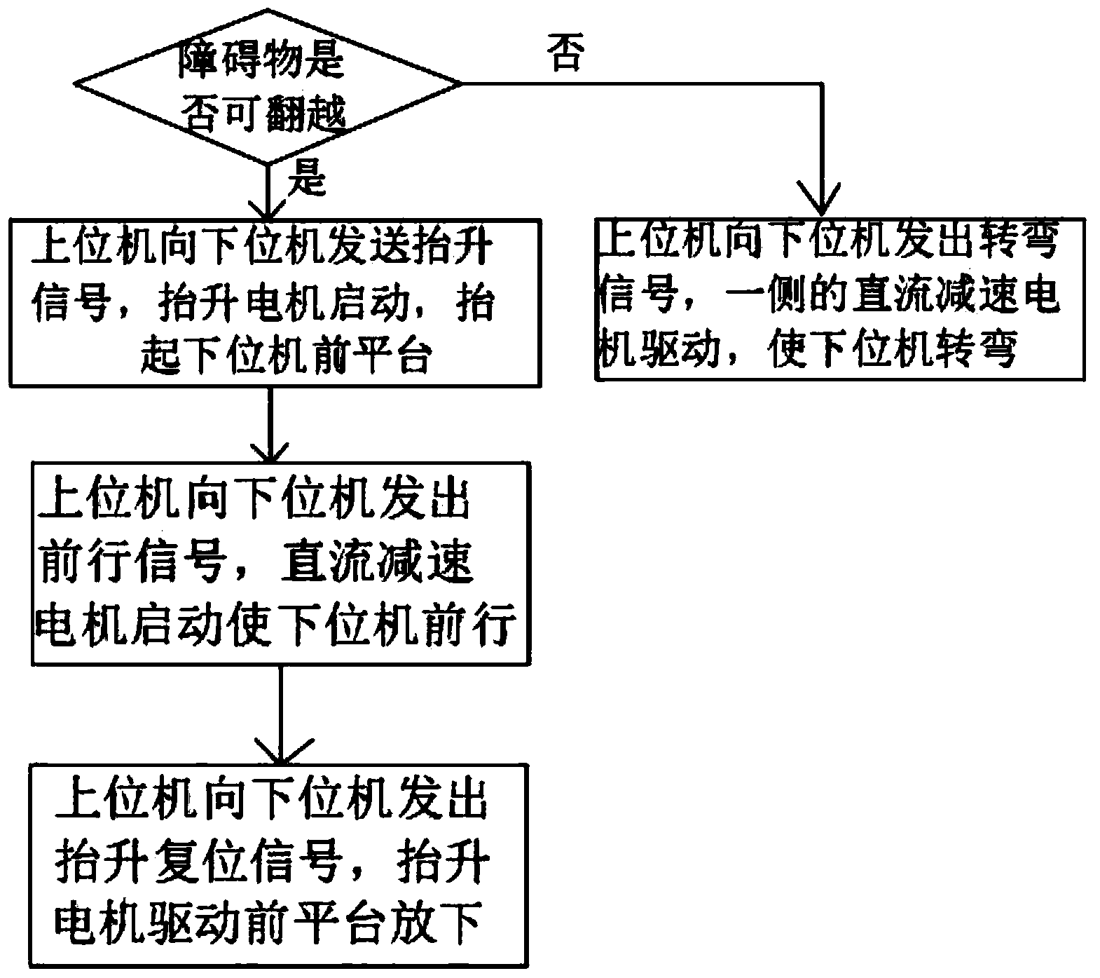

Image

  • EOD (Explosive Ordnance Disposal) robot control system, EOD robot control method and EOD robot using EOD robot control method
  • EOD (Explosive Ordnance Disposal) robot control system, EOD robot control method and EOD robot using EOD robot control method
  • EOD (Explosive Ordnance Disposal) robot control system, EOD robot control method and EOD robot using EOD robot control method

Examples


Embodiment Construction

[0053] The specific implementation manner and working principle of the present invention will be further described in detail below in conjunction with the accompanying drawings.

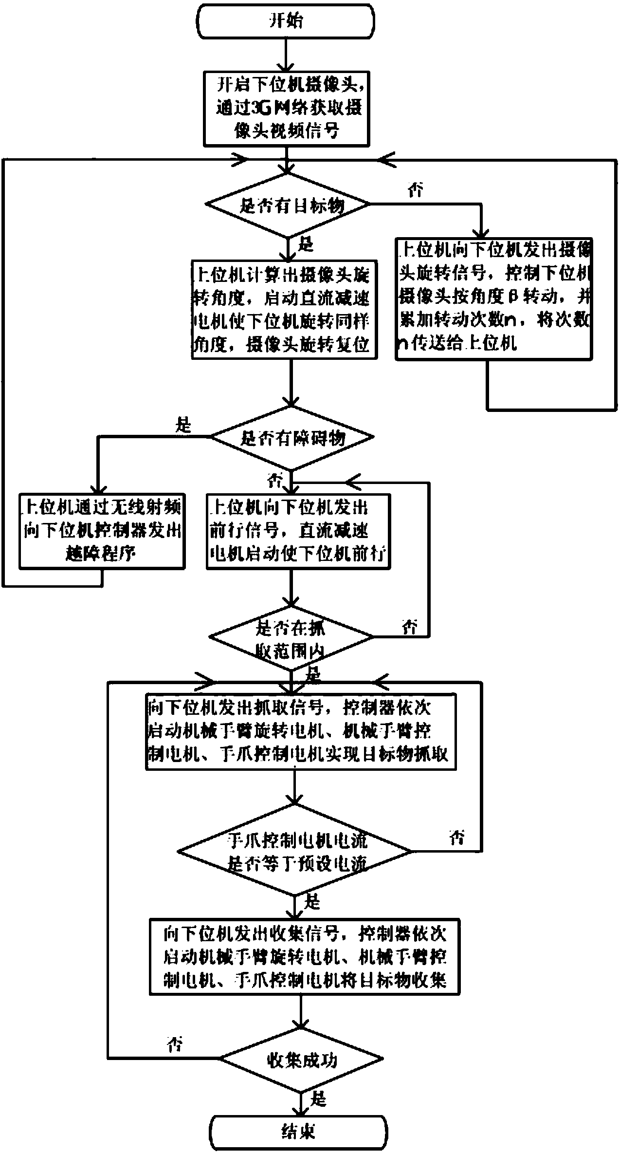
[0054] Such as figure 1 as shown, figure 1 It is a schematic diagram of the overall flow of the control method of the EOD robot of the present invention, a control method of the EOD robot, and the specific steps are:

[0055] A1. Turn on the camera of the lower computer, obtain the video signal of the camera through the 3G network, and enter step A2; start the modules of the upper computer and the lower computer, and the lower computer performs two-way transmission, one route is used to collect video signals from the camera, and the other is routed to the controller to control each motor drive. The upper computer analyzes the video and issues control instructions.

[0056] A2. Judging whether there is a target in the route: when no target is found, go to step A3; when a target is found, go to step...


PUM


Abstract

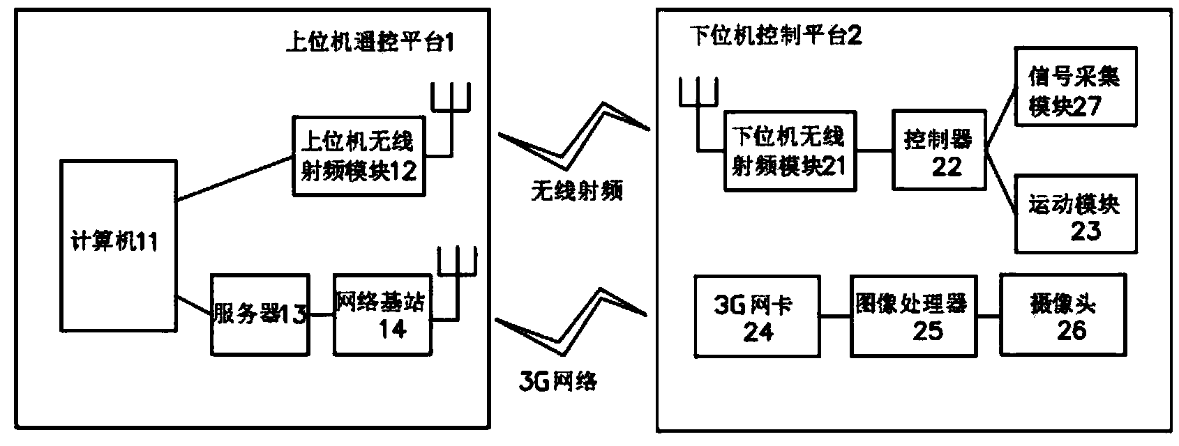
The invention discloses an EOD (Explosive Ordnance Disposal) robot control system. The EOD robot control system is characterized by comprising an upper computer remote control platform and a lower computer control platform, wherein the upper computer remote control platform comprises a computer, a server, an upper computer RFID (Radio Frequency Identification) module and a network base station; the lower computer control platform comprises a lower computer RFID module, a controller, a motion module, a 3G (The 3rd Generation Telecommunication) network card, an image processor, a camera and a signal collecting module. The EOD robot control system disclosed by the invention has the beneficial effects that the size of the EOD robot is minimized, the performance is stable, RFID transmission distance is moderate, and simultaneous monitoring by multiple computers or remote monitoring can be realized. The layout of the EOD robot control system is rationalized, and thus the EOD robot is unlikely to be subjected to accidents such as rollover when in operation. The motion module is high in running accuracy, compact in structure, small in size and good in obstacle crossing performance, the EOD robot is enabled to be stable in walking due to three platforms during a walking process, and the motion of the EOD robot is flexible.

Description

technical field [0001] The invention relates to the field of explosion-discharge robots, in particular to an explosion-discharge robot control system and method and an explosion-discharge robot using the method. Background technique [0002] With the increasingly severe global anti-terrorism situation and frequent terrorist attacks at home and abroad, the armed forces and security departments of various countries have a huge demand for EOD robots. At present, the cost of EOD robots launched in domestic and foreign markets is relatively high, which is not conducive to large-scale promotion. [0003] EOD robots belong to the category of ground mobile robots in unstructured environments, and the research on it abroad started earlier. European and American capitalist countries such as the United Kingdom, France, Germany, and the United States have successively launched technical research on EOD robots. Most of the earliest EOD robots were used for military purposes. With the ...

Claims


Application Information

Patent Timeline
Patent Type & Authority Applications(China)
IPC IPC(8): B25J13/08B25J9/16
CPCB25J11/0025
Inventor 易军郑光胜周伟张元涛李太福
Owner 北京东美森泰科技有限公司
Learn More