Steam-water separator and steam generator simulation body

A steam-water separator and steam generator technology, which is applied to steam separation devices and other directions, can solve the problems of large resistance coefficient, large pressure drop loss and inability to meet the requirements, and achieve the effects of low cost, reduced pressure drop loss and simple structure.

Active Publication Date: 2014-02-05
NUCLEAR POWER INSTITUTE OF CHINA
View PDF6 Cites 5 Cited by
  • Summary
  • Abstract
  • Description
  • Claims
  • Application Information

AI Technical Summary

Problems solved by technology

[0007] The purpose of the present invention is to overcome the disadvantages of the existing steam-water separator with complex structure, large resistance coefficient, large pressure drop loss when the medium flows through, and the inability to meet the requirements of the passive waste heat discharge experiment on the secondary side of the ACP1000. The steam-water separator meets the requirements of the passive waste heat discharge experiment on the secondary side, has a small resistance coefficient, and has a simple structure. At the same time, the steam-water separator can also be applied to other equipment or devices with a low flow rate of the steam-water mixture medium (less than 4m / s).

Method used


Image

  • Steam-water separator and steam generator simulation body
  • Steam-water separator and steam generator simulation body

Examples


Embodiment 1

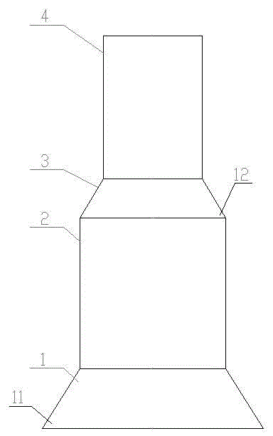
[0038] Such as figure 1 As shown, the steam-water separator is composed of the lower cone section 1, the lower section 2 of the ascending cylinder, the upper cone section 3 and the upper section 4 of the ascending cylinder. The lower cone section 1 and the upper cone section 3 have a wide bottom and a narrow structure. The upper end is connected with the lower end of the lower section 2 of the ascending section, the upper end of the lower section 3 of the ascending section is connected with the lower end of the upper cone section 3, and the upper end of the upper cone section 3 is connected with the lower end of the upper section 4 of the ascending section.

[0039] The diameter of the lower section 2 of the ascending cylinder is greater than the diameter of the upper section 4 of the ascending cylinder.

[0040] The lower cone section 1 is used for introducing the soda-water mixture into the lower section 2 of the ascending cylinder, and the upper cone section 3 is used for i...

Embodiment 2

[0043] Such as figure 1 As shown, in this embodiment, on the basis of Embodiment 1, the angle A11 of the bottom surface of the lower cone section 1 is preferably set to 45°, so that the resistance generated by the soda-water mixture passing through the lower cone section 1 is minimal.

Embodiment 3

[0045] Such as figure 1 As shown, in this embodiment, on the basis of Embodiment 1 or Embodiment 2, the angle B12 of the bottom surface of the upper cone section 3 is preferably set to 45°, so that the resistance generated by the soda mixture passing through the upper cone section 3 is the minimum.


PUM


Abstract

The invention discloses a steam-water separator. The steam-water separator is formed by the lower cone section (1), the ascending cylinder lower section (2), the upper cone section (3) and the ascending cylinder upper section (4); the lower cone section (1) and the upper cone section (3) are of structures with wide lower portions and narrow upper portions; the upper end of the lower cone section (1) is connected with the lower end of the ascending cylinder lower section (2); the upper end of the ascending cylinder lower section (2) is connected with the lower end of the upper cone section (3); the upper end of the upper cone section (3) is connected with the lower end of the ascending cylinder upper section (4). The invention also discloses a steam generator simulation body. According to the steam-water separator and the steam generator simulation body, rotating blades and a dryer are omitted under the condition that the test requirements are met and accordingly the structure is simple and the cost is low.

Description

technical field [0001] The patent of the invention relates to the fields of nuclear industry, thermal power generation and petrochemical industry, in particular to a steam-water separator and a steam generator simulation body. . Background technique [0002] At present, the vertical natural circulation steam generators used in pressurized water reactors mainly include two-stage steam-water separators. After leaving the heat transfer tube bundle, the steam-water mixture first enters the first-stage steam-water separator (rotary vane separator) through the ascending section to remove most of the water, and then enters the second-stage steam-water separator (herringbone plate dryer) for further dehumidification . [0003] The steam separator is an important part of the natural circulation steam generator. The steam-water separator mainly affects the steam quality, and plays an extremely important role in the safe and economical operation of the steam turbine. The structure ...

Claims


Application Information

Patent Timeline
Patent Type & Authority Applications(China)
IPC IPC(8): F22B37/26
Inventor 郗昭袁德文熊万玉荚川卓文彬李朋洲
Owner NUCLEAR POWER INSTITUTE OF CHINA
Why Eureka
Try Eureka