
Spherically-dished rotor type micro-mechanical gyroscope

A mechanical gyroscope and rotor technology, applied in the direction of rotating gyroscopes, etc., can solve the problems of no obvious improvement in the accuracy of rotating micro gyroscopes, small size of the rotor, limitation of rotor speed and stability, etc., and achieve simple and high-efficiency device structure and manufacturing process. The effect of precision and fast movement speed

Inactive Publication Date: 2014-02-05
HARBIN INST OF TECH
View PDF5 Cites 1 Cited by
  • Summary
  • Abstract
  • Description
  • Claims
  • Application Information

AI Technical Summary

Problems solved by technology

However, because the traditional suspended rotor gyroscope uses electromagnetic force or electrostatic force to levitate the rotor, the rotor is small in size, the speed and stability of the rotor are limited, and the accuracy of the rotary micro-gyroscope has not been significantly improved.

Method used


Image

  • Spherically-dished rotor type micro-mechanical gyroscope
  • Spherically-dished rotor type micro-mechanical gyroscope

Examples


Embodiment Construction

[0013] The present invention will be described in further detail below in conjunction with the accompanying drawings: the present embodiment is implemented on the premise of the technical solution of the present invention, and detailed implementation is provided, but the protection scope of the present invention is not limited to the following embodiments.

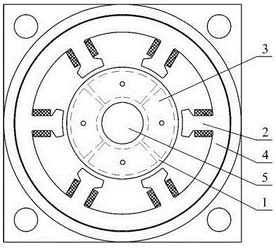
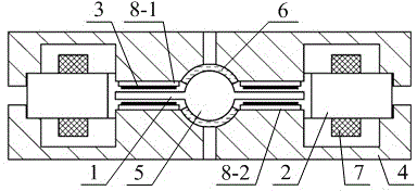
[0014] Such as figure 1 and figure 2 As shown, a ball-and-disk rotor micromechanical gyro involved in this embodiment includes: a gyro rotor 1, six stators 2, eight detection electrodes 3, a shell 4 with a concave spherical surface, a spherical bearing 5, and a lubricating oil layer 6. Drive coil 7, upper insulating layer 8-1 and lower insulating layer 8-2. The gyro rotor 1 is arranged inside the housing 4 with a concave spherical surface, and the gyro rotor 1 and the spherical bearing 5 are processed integrally or tightly Assembled to form a ball-disc rotor, the spherical bearing 5 is rotationally connected with the she...


PUM


Abstract

The invention provides a spherically-dished rotor type micro-mechanical gyroscope. A gyroscope rotor and a special bearing are integrally machined or compactly assembled and formed, the spherical bearing is rotatably connected with a shell with a concave spherical surface through a lubricating oil layer, stators are clamped on the edge of the shell with the concave spherical surface by adopting silicon steel sheets and are tightly connected with the outer wall of the shell with the concave spherical surface, eight detection electrodes are respectively connected with the shell with the concave spherical surface through an upper insulation layer and a lower insulation layer, drive coils are respectively wound on the six stators, numbers of turns of the drive coils are completely same, and the stators are positioned at the outer part of the gyroscope rotor and is positioned at the same plane together with the gyroscope rotor. A cavity body can be manufactured in a mechanical punching mode, the spherically-dished gyroscope rotor is integrally machined or assembled and formed, the resistance can be reduced when the rotor rotates when the spherical bearing fully lubricates the rotor, the movement speed of the rotor is high, the stability is high, and the deflection damping moment of the spherically-dished gyroscope rotor is very small by adopting the spherical bearing, and thus the relatively high precision is achieved.

Description

technical field [0001] The invention relates to a ball-and-disk rotor type micro-mechanical gyroscope, which belongs to the technical field of mechanical gyroscopes. Background technique [0002] A gyroscope is a sensing device that measures the angle or velocity of an object relative to inertial space. MEMS micro gyro is the product of the combination of MEMS technology and inertial technology, and it is one of the main development directions of gyro technology in the future. MEMS micro gyro has the advantages of small size, light weight, low power consumption, impact resistance, and can be applied to relatively harsh environmental conditions. It has become an important core in navigation, guidance, and control systems in the fields of aviation, aerospace, and micro-armament equipment. device. [0003] At present, the micro gyroscope mainly adopts the vibrating structure, and the vibrating gyroscope is usually driven by electrostatic or electromagnetic force, so that the ...

Claims


Application Information

Patent Timeline
IPC IPC(8): G01C19/08
CPCG01C19/08
Inventor 刘晓为陈伟平张海峰尹亮
Owner HARBIN INST OF TECH
Learn More