Method and device for measuring optical delay

A technology of optical delay and measurement method, which is applied in the field of high-precision time delay measurement, and can solve problems such as inability to achieve delay control, millimeter-level length errors, etc.

Inactive Publication Date: 2014-02-05
INST OF FLUID PHYSICS CHINA ACAD OF ENG PHYSICS
View PDF4 Cites 14 Cited by
  • Summary
  • Abstract
  • Description
  • Claims
  • Application Information

AI Technical Summary

Problems solved by technology

[0005] Since the ultra-short delay (corresponding to the sub-millimeter length of the optical fiber) can only be measured by off-line optical methods, and the fiber cutting and welding, or the flange connection process will introduce millimeter-level length errors, so that precise delay control cannot be achieved
Using photoelectric conversion for measurement will also introduce measurement errors of several picoseconds due to the electrical inertia effect in the conversion

Method used


Image

  • Method and device for measuring optical delay
  • Method and device for measuring optical delay
  • Method and device for measuring optical delay

Examples


Embodiment 1

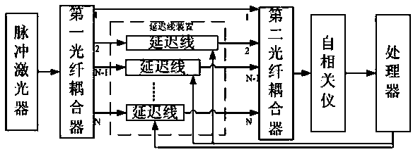
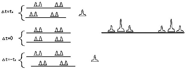
[0058] Embodiment 1: The device includes a delay line, the first fiber coupler is a 1*2 fiber coupler, and the second fiber coupler is a 2*1 fiber coupler. Such as figure 2 As shown, the input light of the pulsed laser is divided into two paths by the first fiber coupler, one of which is connected to the fiber delay line for delay control, and then connected by the second coupler to combine the two paths of optical pulses with time difference into one path . If the delay line delay is t 0 , then the distance between the undelayed laser beam signal and the laser beam signal passing through the delay line is t 0 . Similarly, if it is necessary to delay the laser beam pulse by N times, select 1*N first fiber couplers, N*1 second fiber couplers and N−1 delay lines.

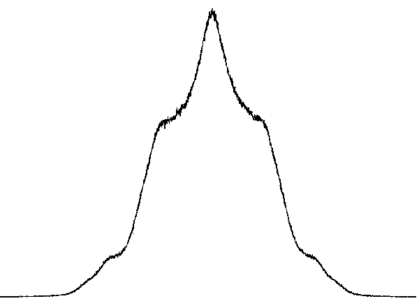
[0059] The delayed laser beam pulse is input to the autocorrelator, and the optical path of the autocorrelator is adjusted until the autocorrelation signal appears. Since the rotating arm of the autocorrelator c...

Embodiment 2

[0062] Embodiment 2: The device includes 7 delay lines, the first fiber coupler is a 1*8 fiber coupler, and the second fiber coupler is an 8*1 fiber coupler. The input light of the pulsed laser is divided into 8 paths on average through the first fiber coupler, the first path is connected to the first input port of the second fiber coupler, the second path of the first fiber coupler to the eighth path of the second fiber coupler are respectively Connect the delay line for delay control, and then use the 8*1 fiber coupler to combine the 8 optical pulses with time difference into one. If the delay line delay is t 0 , then the distance between the undelayed laser beam signal and the laser beam signal passing through the delay line is t 0 、2t 0 、3t 0 、4t 0 、5t 0 、6t 0 、7t 0 .

[0063] The laser beam pulses passing through the second fiber coupler are input to the autocorrelator, and the optical path of the autocorrelator is adjusted until an autocorrelation signal appears....


PUM


Abstract

The invention relates to the technical field of high-precision time delay measurement, in particular to a method and device for measuring optical delay with an optical autocorrelation method. The method for precisely measuring the delay based on optical autocorrelation is provided to solve the problems in the prior art, the time delay smaller than 10 picoseconds can be measured, the largest measuring range is determined by the measuring range of an autocorrelator, and relative measuring precision is superior to 1%. The method and device are achieved through the cooperation of a pulse laser, a first optical fiber coupler, a delay line device, a second optical fiber coupler, the autocorrelator, a processor and the like. The method and device are suitable for the precise measurement of subnanosecond time delay in the optical fiber and free space optical field.

Description

technical field [0001] The invention relates to the technical field of high-precision time delay measurement, in particular to an optical delay measurement method and device of an optical autocorrelation method. Background technique [0002] Optical sampling is a technique for sampling high-bandwidth analog signals through optical methods, which has a bandwidth that cannot be achieved by traditional photodetectors and oscilloscopes. With the development of optical communication, especially optical sampling technology, the optical sampling rate obtained by "replicating" optical pulses through optical delay methods continues to increase. Taking the optical sampling rate of 100GSa / s as an example, the optical delay of adjacent channels is required to be 10ps. And a higher sampling rate corresponds to a smaller optical delay. At the same time, the accuracy of optical delay is directly related to the signal-to-noise ratio of optical sampling, so the accurate measurement of optic...

Claims


Application Information

Patent Timeline
Patent Type & Authority Applications(China)
IPC IPC(8): G01J9/00
Inventor 陶世兴赵新才杨丽玲温伟峰李建中肖正飞胡腾阳庆国刘宁文彭其先李泽仁
Owner INST OF FLUID PHYSICS CHINA ACAD OF ENG PHYSICS
Why Eureka
Try Eureka