Physical standard battery potential difference meter experiment instrument and method for measuring potential difference by means of the experiment instrument

A technology of potentiometer and standard battery, which is applied to AC/DC potential difference measuring devices, instruments, educational appliances, etc. It can solve the problems of poor measurement accuracy of potentiometer experimental instrument and poor stability of electromotive force value, etc., so as to improve measurement accuracy , good stability and adjustable size

Inactive Publication Date: 2014-02-05
NORTHEAST FORESTRY UNIVERSITY
View PDF1 Cites 3 Cited by
  • Summary
  • Abstract
  • Description
  • Claims
  • Application Information

AI Technical Summary

Problems solved by technology

[0003] In order to solve the problem that the existing chemical formula standard battery is easily affected by the external environment, the stability of the output electromotive force value is poor, and the measurement accuracy of the

Method used


Image

  • Physical standard battery potential difference meter experiment instrument and method for measuring potential difference by means of the experiment instrument

Examples


Example Embodiment

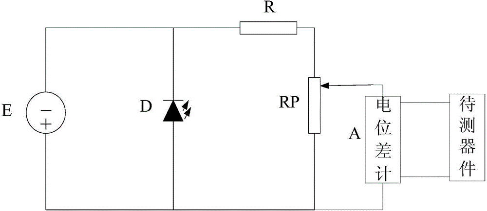
[0012] Specific implementation mode 1. Combination figure 1 Describe this embodiment, the potentiometer experimental instrument of the physical type standard battery described in this embodiment, the experimental instrument includes a DC stabilized power supply E, a light-emitting diode D, a resistor R, a potentiometer RP, and a potentiometer A;

[0013] The positive pole of the DC stabilized power supply E is connected to the anode of the light-emitting diode D and one end of the potentiometer RP at the same time, the cathode of the light-emitting diode D is connected to the negative pole of the DC stabilized power supply E and one end of the resistor R at the same time, and the other end of the resistor R is connected to the potentiometer RP The other end of the potentiometer A; the positive signal input terminal of the potentiometer A is connected to the positive pole of the DC power supply E, and the negative signal input terminal of the potentiometer A is connected to the ...

Example Embodiment

[0017] Specific Embodiment 2. This embodiment is a further description of the potentiometer experimental instrument for a physical standard battery described in Specific Embodiment 1. The DC stabilized power supply E adopts a DC stabilized power supply with a voltage of 3V.

Example Embodiment

[0018] Specific Embodiment 3. This embodiment is a further description of the potentiometer experimental instrument for a physical standard battery described in Specific Embodiment 1. The light-emitting diode D is a light-emitting diode with a power of 1W.


PUM


Abstract

The invention discloses a physical standard battery potential difference meter experiment instrument and a method for measuring potential difference by means of the experiment instrument, and relates to the potential difference meter experiment instrument and the method for measuring the potential difference by means of the experiment instrument. The problems that due to the facts that an existing chemical-type standard battery is easily influenced by external environment, and the stability of the electro-dynamic potential value output by the chemical battery is poor, the potential difference meter experiment instrument is poor in measuring accuracy are solved. The positive electrode of a direct-current voltage-stabilized power source is connected with the anode of a light-emitting diode and one end of an RP at the same time, the cathode of the light-emitting diode is connected with the negative electrode of the direct-current voltage-stabilized power source and one end of a resistor at the same time, the other end of the resistor is connected with the other end of the RP, the positive electric signal input end of a potential difference meter is connected with the positive electrode of the direct-current voltage-stabilized power source, and the negative electric signal input end of the potential difference meter is connected with the movable end of the RP. The experiment instrument is utilized for measuring the potential difference of a device to be measured, the movable end of the RP is adjusted, and the measurement of the potential difference of the device to be measured is achieved. The physical standard battery potential difference meter experiment instrument is applicable to measuring the potential difference.

Description

technical field [0001] The invention relates to a potentiometer experimental instrument and a method for measuring potential difference by using the potentiometer experimental instrument. Background technique [0002] The standard battery used in the potentiometer tester is generally a chemical battery, which is greatly affected by temperature, especially the change of the indoor ambient temperature will cause the change of the output electromotive force of the chemical standard battery. Therefore, it must be calibrated according to the law of temperature change before each use. The chemical standard battery can only be used; and the chemical standard battery cannot be tilted, let alone shaken or inverted, otherwise the chemical substances in the glass tube will be mixed together, which will affect the electromotive force value and stability, and even cannot be used; in addition, the chemical standard battery also cannot be used. It is greatly affected by light, because the ...

Claims


Application Information

Patent Timeline
IPC IPC(8): G09B23/18G01R17/20
Inventor 李景奎戚大伟张中兴崔金刚
Owner NORTHEAST FORESTRY UNIVERSITY
Why Eureka
Try Eureka