Device and method for correcting power factor

A power factor correction and power factor technology, applied in output power conversion devices, sustainable manufacturing/processing, high-efficiency power electronic conversion, etc., which can solve the complex modulation of PWM and PFM controllers and low total harmonic distortion of input current , high dynamic characteristics and other issues, to achieve the effect of power factor correction, fast transient response, and improved dynamic performance

Inactive Publication Date: 2014-02-05
WUHAN UNIV OF TECH
View PDF2 Cites 5 Cited by
  • Summary
  • Abstract
  • Description
  • Claims
  • Application Information

AI Technical Summary

Problems solved by technology

The two-stage PFC scheme has excellent performance, such as low total harmonic distortion of input current and high power factor; however, the two-stage PFC scheme increases cost and complexity because it has at least two switch tubes and two sets of control circuits
[0004] In recent years, the methods of improving power factor all need to be implemented by adding peripheral circuits on the basis of single-stage PFC circuits, but the traditional control strategy contains the following shortcomings: 1) During the entire process of circuit operation, PID control is difficult to maintain a high 2) The modulation of the PWM and PFM controllers is complicated; 3) The PFC stage and the DC / DC stage will affect each other during operation, but the two relatively independent controllers have not been connected before, and the dynamic performance cannot be achieved in a short period of time. improved over time

Method used


Image

  • Device and method for correcting power factor
  • Device and method for correcting power factor
  • Device and method for correcting power factor

Examples


Embodiment Construction

[0036] In order to make the object, technical solution and advantages of the present invention clearer, the present invention will be further described in detail below in conjunction with the accompanying drawings and embodiments. It should be understood that the specific embodiments described here are only used to explain the present invention, not to limit the present invention.

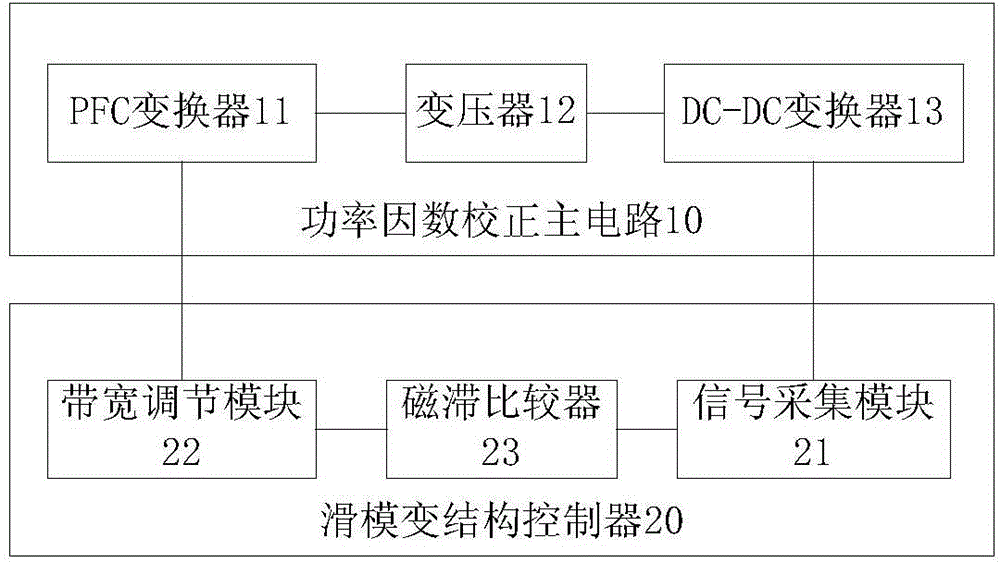
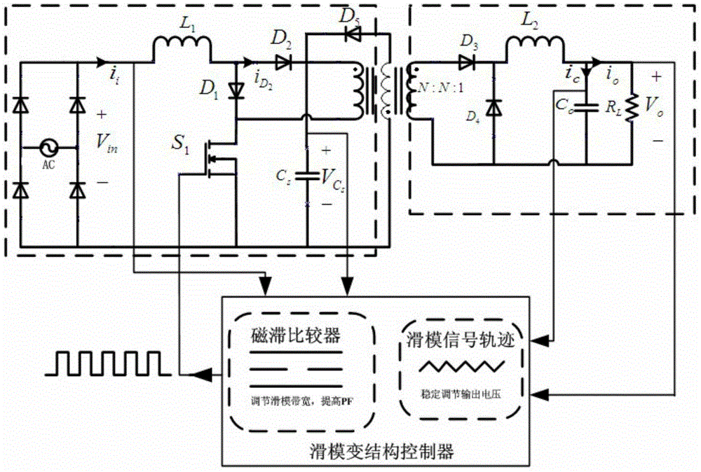
[0037] The power factor correction device of the embodiment of the present invention includes a power factor correction main circuit 10 and a sliding mode variable structure controller 20 . In one embodiment of the present invention, as figure 1 As shown, the power factor correction main circuit 10 includes a PFC converter 11 and a DC-DC converter 13; the PFC converter 11 and the DC-DC converter 13 are connected through a transformer 12;

[0038] The sliding mode variable structure controller 20 includes a signal acquisition module 21, a bandwidth adjustment module 22 and a hysteresis comparator 2...


PUM


Abstract

The invention discloses a device and method for correcting a power factor. The device comprises a main power factor correcting circuit and a sliding mode variable structure controller. The sliding mode variable structure controller comprises a signal collecting module, a bandwidth adjusting module and a hysteresis comparator. The bandwidth adjusting module is used for receiving input voltage and buffering capacitor voltage of the main power factor correcting circuit and outputting a bandwidth, and the output bandwidth is changed along with the changes of the input voltage to change the frequency of a switch tube of the main power factor correcting circuit. The signal collecting module is used for collecting the feedback voltage of an output signal of the main power factor correcting circuit. The hysteresis comparator is used for producing a sliding mode signal track according to the comparison result between the feedback voltage collected by the signal collecting module and the given reference voltage, the sliding mode signal track is compared with the bandwidth, a periodical control signal is produced, and the duty ratio of the main power factor correcting circuit is adjusted through the control signal to change the output voltage of the main power factor correcting circuit.

Description

technical field [0001] The invention relates to the field of switching power supplies, in particular to a power factor correction device and method. Background technique [0002] In recent years, switching power supplies with superior performance have replaced linear power supplies and become the main power equipment in electronic systems. In a typical switching power supply, the AC power grid is generally directly connected in parallel with a large capacitor after passing through a rectifier bridge to obtain a relatively flat DC voltage. Although this traditional rectifier can obtain a relatively flat DC voltage, it is a combination of a nonlinear element and an energy storage element. It only has input current at the peak part of the input AC voltage, so the input current is seriously distorted. , showing a pulse shape. This pulse-shaped input current contains a large number of harmonics, which seriously pollutes the power grid. In order to reduce the harmonic pollution...

Claims


Application Information

Patent Timeline
Patent Type & Authority Applications(China)
IPC IPC(8): H02M1/42
CPCY02B70/126Y02B70/10Y02P80/10
Inventor 朱国荣王浩然刘卫星王菁陈伟刘芙蓉徐应年
Owner WUHAN UNIV OF TECH
Why Eureka
Try Eureka