
Location fingerprint positioning method and device

A fingerprint positioning and fingerprint technology, which is applied in location information-based services, electrical components, wireless communication, etc., can solve the problems of increasing the complexity of positioning algorithms and affecting real-time positioning

Inactive Publication Date: 2014-02-05
BEIJING UNIV OF POSTS & TELECOMM
View PDF8 Cites 17 Cited by
  • Summary
  • Abstract
  • Description
  • Claims
  • Application Information

AI Technical Summary

Problems solved by technology

[0008] However, if in a large-scale indoor environment, a large number of location fingerprints need to be collected according to the above-mentioned positioning technology based on location fingerprints that have nothing to do with ranging, the fingerprint map formed by a large number of location fingerprints will increase the complexity of the positioning algorithm, affecting real-time positioning

Method used


Image

  • Location fingerprint positioning method and device
  • Location fingerprint positioning method and device
  • Location fingerprint positioning method and device

Examples


Embodiment 1

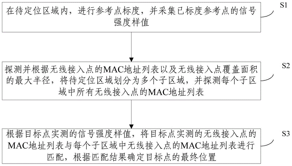
[0056] In order to solve the above problems, an embodiment of the present invention provides a location fingerprint positioning method, such as figure 1 As shown, the method includes:

[0057]S1: In the area to be positioned, perform reference point calibration and collect signal strength samples of the scaled reference points;

[0058] S2: Detect and divide the area to be located into multiple sub-areas according to the MAC address list of the wireless access point and the maximum radius of the coverage area of ​​the wireless access point, and detect the MAC address list of all wireless access points in each sub-area;

[0059] S3: According to the signal strength samples measured at the target point, match the MAC address list of the wireless access point measured at the target point with the MAC address list of the wireless access point in each sub-area, and determine the final position of the target point according to the matching result .

[0060] The present invention p...

Embodiment 2

[0096] In order to solve the above technical problems, the embodiment of the present invention also provides a location fingerprint positioning device, such as Figure 4 shown, including:

[0097] A reference point scale module 201, configured to perform reference point scale in the area to be positioned;

[0098] The position fingerprint establishment module 202 is used for establishing the position fingerprint according to the signal strength sample value of each scaled reference point;

[0099] The location fingerprint building module includes:

[0100] The location fingerprint vector building module is used to obtain the mean value of the signal strength samples in each direction of each reference point, and label the mean value of the signal strength samples in each direction of each test point as a location fingerprint vector, and after the label The location fingerprint vectors of are recorded in the fingerprint map.

[0101] The detection module 203 is used to detec...


PUM


Abstract

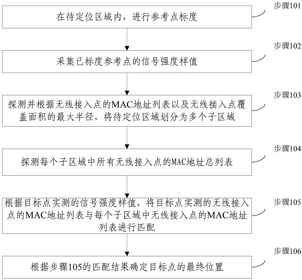
The invention provides a location fingerprint positioning method and a device thereof, relating to the technical field of wireless positioning. The method comprises a step of carrying out reference point calibration and collecting the signal strength sample value of a calibrated reference point in an area to be positioned, a step of detecting and dividing the area to be positioned into a plurality of sub areas according to the MAC address list of a wireless access point and the largest diameter of a wireless access point coverage area and detecting the MAC address lists of all wireless access points in each of the sub areas, and a step of matching the MAC address lists of wireless access points of target point actual measurement with the MAC address lists of the wireless access points in each of the sub areas and determining the final position of the target point according to a matching result. According to the method and the device, through carrying out reference point calibration in the area to be positioned, high positioning accuracy is obtained, the area to be positioned is divided into a plurality of sub areas, and the computational complexity of high positioning is reduced. In addition, through the reduction of the computational complexity, the real-time positioning of the target point can be realized.

Description

technical field [0001] The invention relates to the technical field of wireless positioning, in particular to a position fingerprint positioning method and device. Background technique [0002] In recent years, wireless positioning technology can be divided into two types: ranging-based positioning and non-ranging-based positioning. For example, traditional positioning technologies based on TOA (Time of Arrival) / TDOA (Time Difference of Arrival) / RSS (Received Signal Strength) are calculated based on time or signal strength parameters The approximate distance between the base station and the target point, and then use the geometric position relationship between the base stations to locate the target point. However, ranging-based positioning technology is easily interfered by non-line-of-sight situations, and its positioning accuracy and stability are poor for wireless channels with high complexity and strong time-varying characteristics. Therefore, in indoor scenarios, many...

Claims


Application Information

Patent Timeline
Patent Type & Authority Applications(China)
IPC IPC(8): H04W4/02H04W64/00
Inventor 崔琪楣陶小峰邓金刚史玉龙张雪菲
Owner BEIJING UNIV OF POSTS & TELECOMM
Learn More