
Hall-effect thruster

A Hall effect and thruster technology, applied in the field of plasma thrusters, can solve problems such as limiting the life of thrusters, decreasing engine efficiency, and accelerating engine aging

Inactive Publication Date: 2014-02-05
SN DETUDE & DE CONSTR DE MOTEURS DAVIATION (S N E C M A)
View PDF7 Cites 6 Cited by
  • Summary
  • Abstract
  • Description
  • Claims
  • Application Information

AI Technical Summary

Problems solved by technology

Given their energy, these ions can corrode the ceramics of the discharge channel, thereby limiting the lifetime of the thruster
[0011] The second limitation is that at high levels of specific impulse (Isp), engine efficiency decreases and engine aging accelerates
However, using a grid has certain drawbacks

Method used


Image

  • Hall-effect thruster
  • Hall-effect thruster
  • Hall-effect thruster

Examples


Embodiment Construction

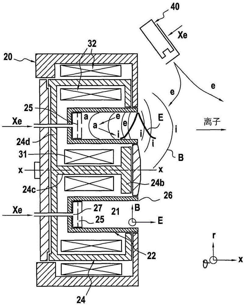
[0028] The present invention relates to the above referenced figure 2 The general structure of the Hall effect thruster is described.

[0029] Although often referred to as "stationary plasma thrusters," conventional Hall-effect thrusters are unstable in operation. Several frequency ranges in the range of 20 kilohertz (kHz) to several gigahertz can be considered.

[0030] At low frequencies, conventional Hall effect thrusters are characterized primarily by the following phases:

[0031] a) filling the discharge channels with inert atoms of propellants such as xenon;

[0032] b) ionize the inert atoms with energetic electrons in the lower half of the thruster; and

[0033] c) The ions that have been produced are accelerated and ejected by means of an electric field E proportional to the discharge voltage Ud of the thruster.

[0034] The same three-stage loop restarts periodically.

[0035] image 3 A simplified model showing vibrations in a Hall effect thruster.

[0036]...


PUM


Abstract

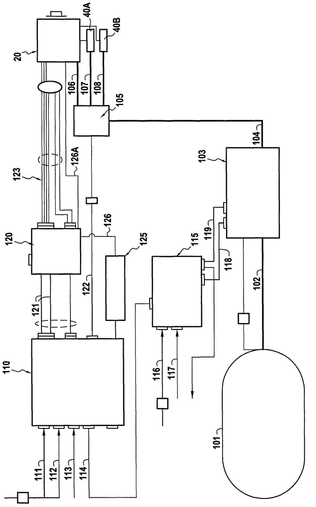
The invention relates to a Hall-effect thruster that includes at least one high-pressure gas tank (101), a pressure-control module (103), a device for controlling the gas flow rate (105), an ionisation channel, a cathode (40A, 40B) arranged adjacent to the output of the ionisation channel, an anode combined with the ionisation channel, a power supply unit (110), an electric filter (120), and coils for creating a magnetic field around the ionisation channel. The Hall-effect thruster further includes an additional power supply unit (125) for applying a pulsed voltage between the anode and the cathode (40A, 40B).

Description

technical field [0001] The present invention relates to Hall effect thrusters, also known as stationary plasma thrusters. Background technique [0002] A Hall effect thruster basically comprises an ionizing discharge channel associated with an anode, a cathode arranged near the outlet of the ionizing discharge channel. The ionization discharge channels are made of insulating materials such as pottery. Magnetic circuits and electromagnetic coils surround the ionization discharge channel. An inert gas such as xenon is injected into the back of the discharge channel and into the cathode. The internal gas is ionized in the ionization discharge channel by collision with the electrons emitted by the cathode. The generated ions are accelerated and ejected by the axial electric field generated between the anode and cathode. Within the channel, the magnetic circuit and electromagnetic coil generate a substantially radial magnetic field. [0003] figure 2 is an axial cross-secti...

Claims


Application Information

Patent Timeline
Patent Type & Authority Applications(China)
IPC IPC(8): F03H1/00
CPCF03H1/0075F03H1/0087F03H1/0018F03H1/0068F03H1/0062
Inventor 斯蒂芬·约瑟夫·苏尔巴什弗雷德里克·马尚迪斯迈克尔·奥贝格
Owner SN DETUDE & DE CONSTR DE MOTEURS DAVIATION (S N E C M A)
Learn More