A hydraulic system and a method for controlling a hydraulic system

A hydraulic system and hydraulic technology, applied in the field of controlling hydraulic systems, can solve problems such as power source function and/or life damage

Inactive Publication Date: 2014-02-05
VOLVO CONSTR EQUIP
View PDF7 Cites 11 Cited by
  • Summary
  • Abstract
  • Description
  • Claims
  • Application Information

AI Technical Summary

Problems solved by technology

This in turn means that the power (especially torque) required from the power source may vary over time, and changes in the power

Method used


Image

  • A hydraulic system and a method for controlling a hydraulic system
  • A hydraulic system and a method for controlling a hydraulic system
  • A hydraulic system and a method for controlling a hydraulic system

Examples


Embodiment Construction

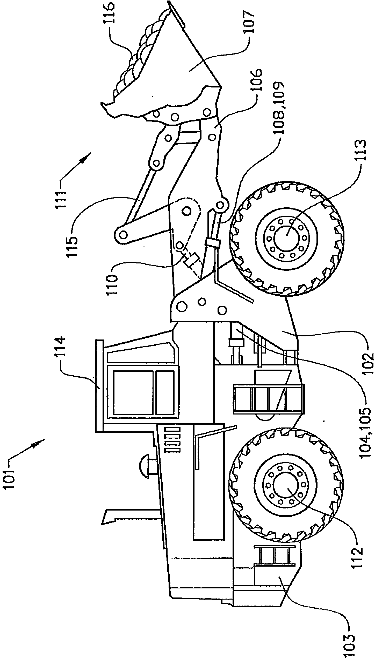
[0056] In the following, the invention will be described with respect to a construction machine in the form of a wheel loader 101 . The wheel loader 101 should be regarded as an example of a construction machine to which the hydraulic system according to the present invention can be applied. The wheel loader 101 includes a front vehicle section 102 and a rear vehicle section 103 . Both vehicle parts 102 , 103 comprise a frame and wheels arranged on transaxles 112 , 113 . The rear vehicle section 103 includes a cab 114 . The two vehicle parts 102, 103 are connected to each other in such a way that they can be moved about a vertical axis relative to the pivot each other. Accordingly, the hydraulic cylinders 104, 105 are arranged on different sides of the center line and extend in the longitudinal direction of the vehicle for steering or turning the wheel loader 101 by means of these hydraulic cylinders. In other words, the wheel loader 101 is frame steerable.

[0057] The w...


PUM


Abstract

As such, the present invention relates to a hydraulic system (10) for a working machine (101). The hydraulic system (10) comprises a hydraulic actuator (12) and a first hydraulic machine (14) for supplying fluid to the hydraulic actuator (12). The hydraulic system (10) further comprises a hydraulic transformer (28) for supplying fluid to the hydraulic actuator (12) in parallel with the first hydraulic machine (14), and an accumulator (38) for fluid. The hydraulic transformer (28) comprises a first port (30) and a second port (32) and the transformer (38) is adapted to transform a first pressure and a first flow at the first port (30) to a second pressure and a second flow at the second port (32). The second port (32) of the hydraulic transformer (28) is in fluid communication with the hydraulic actuator (28) and the first port is in communication with the accumulator (38).

Description

technical field [0001] The invention relates to a hydraulic system according to the preamble of claim 1 . Furthermore, the invention relates to a method for controlling a hydraulic system according to the preamble of claim 12 . Background technique [0002] Hydraulic systems are used in many technical fields. For example, many types of construction machinery (eg wheel loaders, excavators, etc.) are often equipped with at least one hydraulic system. [0003] A hydraulic system typically includes hydraulic machinery (such as a hydraulic pump) adapted to supply hydraulic power (that is, hydraulic flow and / or hydraulic pressure) to the hydraulic system and that is typically powered by a power source (such as an engine or electric motor) drive. When the hydraulic system is installed in construction machinery, the hydraulic machinery is usually driven by the prime mover of the construction machinery. [0004] In construction machinery, the hydraulic machine may be driven by a ...

Claims


Application Information

Patent Timeline
IPC IPC(8): F15B21/14E02F9/22F15B3/00F16H61/4096
CPCE02F9/2235E02F9/2242F15B2211/214E02F9/2217F15B11/00F15B2211/625F15B2211/20546F16H61/4096E02F9/2296F15B2211/26F15B2211/6303F15B2211/6313F15B2211/6346F15B2211/6655F15B13/02
Inventor 基姆·海布勒克罗兰德·维克托
Owner VOLVO CONSTR EQUIP
Why Eureka
Try Eureka