
Radiation protection material manufacturing method

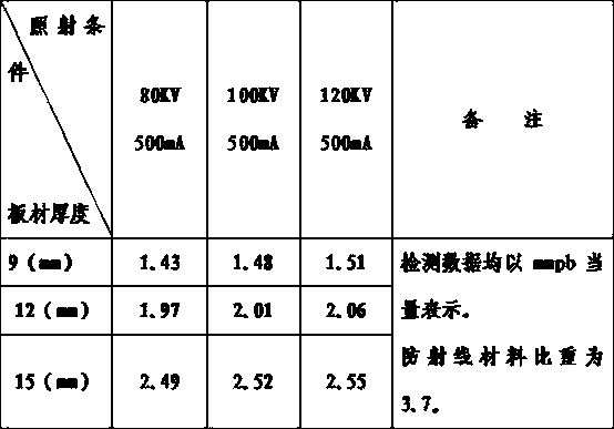
A radiation protection and manufacturing method technology, applied in the direction of manufacturing tools, ceramic molding machines, shielding, etc., can solve the problems of high radiation protection cost of lead plates, surrounding environmental pollution, environmental pollution, etc., to achieve protection from scattered rays, Reduce secondary rays, good effect of anti-rays

Inactive Publication Date: 2014-02-12
湖南康宁达医疗科技股份有限公司
View PDF6 Cites 0 Cited by
  • Summary
  • Abstract
  • Description
  • Claims
  • Application Information

AI Technical Summary

Problems solved by technology

[0002] At present, the existing radiation protection materials mainly adopt lead plates and lead products, which have the following disadvantages: 1. They are not environmentally friendly, harmful to the human body, and pollute the environment. Because lead and lead products are easily oxidized in the air, Pb2O3 or Pb3O4 can be free in the air at the same time, increasing the lead content in the air, leading to contact poisoning or respiratory poisoning, producing a series of poisoning symptoms, and also polluting the surrounding environment; 2. The cost is high, and lead is a heavy metal. In recent years, domestic and international The market price has risen year after year, and the price of lead plates has reached 18,000 yuan / ton. The cost of using lead plates for radiation protection is relatively high; 3. The protection effect is not ideal: lead plates have a high density, although they have strong protection against radiation. But it is easy to produce secondary rays and scattered rays, and secondary rays and scattered rays can cause harm to the body of the staff; 4. The construction is difficult, because the lead plate is soft, when using the lead plate and lead products to prevent rays, All need to use other supporting materials, which increases the difficulty of construction and increases the construction cost

Method used


Image

  • Radiation protection material manufacturing method

Examples


Embodiment 1

[0010] 1. Mixing materials: 40% iron ore powder, 40% manganese ore powder, 10% copper ore powder, 10% unsaturated polyester resin, and the rest are additives.

[0011] 2. The above-mentioned materials are weighed, batched, stirred, and then sent to a vibration pressure molding machine. After being formed by vacuum vibration and pressure, they can be cured at room temperature or heated and cured at 50°C-180°C in a tunnel furnace or box-type cured. The furnace is heated and cured at 50°C-180°C. Then it is made into a standard radiation protection plate after thickness setting, polishing and trimming.

Embodiment 2

[0013] 1. Mixing materials: 45% iron ore powder, 35% manganese ore powder, 15% copper ore powder, 5% unsaturated polyester resin, and the rest are additives.

[0014] 2. The above-mentioned materials are weighed, batched, stirred, and then sent to a vibration pressure molding machine. After being formed by vacuum vibration and pressure, they can be cured at room temperature or heated and cured at 50°C-180°C in a tunnel furnace or box-type cured. The furnace is heated and cured at 50°C-180°C. Then it is made into a standard radiation protection plate after thickness setting, polishing and trimming.


PUM


Abstract

The invention discloses a radiation protection material manufacturing method. The method comprises the following steps of weighing and mixing, by weight percentage, 40-50% of powdered iron ore, 30-40% of powdered manganese ore, 10-20% of powdered copper ore and 5-15% of unsaturated polyester resin with additives as balance; then sending the mixture into a vibration compression moulding press for vacuum compression moulding or room-temperature curing or heating curing in a tunnel furnace at 50-180 DEG C or heating curing in a box-type curing furnace at 50-180 DEG C; performing thicknessing, polishing and trimming to obtain standard radiation protection plates. The radiation protection material manufacturing method is environmentally friendly, economical, good in radiation protection effects and simple in operation, thereby being an ideal radiation protection material manufacturing method.

Description

technical field [0001] The invention relates to the field of radiation protection materials. Background technique [0002] At present, the existing radiation protection materials mainly adopt lead plates and lead products, which have the following disadvantages: 1. They are not environmentally friendly, harmful to the human body, and pollute the environment. Because lead and lead products are easily oxidized in the air, Pb2O3 or Pb3O4 can be free in the air at the same time, increasing the lead content in the air, leading to contact poisoning or respiratory poisoning, producing a series of poisoning symptoms, and also polluting the surrounding environment; 2. The cost is high, and lead is a heavy metal. In recent years, domestic and international The market price has risen year after year, and the price of lead plates has reached 18,000 yuan / ton. The cost of using lead plates for radiation protection is relatively high; 3. The protection effect is not ideal: lead plates have...

Claims


Application Information

Patent Timeline
Patent Type & Authority Applications(China)
IPC IPC(8): B28B1/08C04B26/18
CPCB28B1/082B28B11/243C04B26/18G21F1/106C04B18/12
Inventor 唐峥
Owner 湖南康宁达医疗科技股份有限公司
Learn More