
Ingot furnace with movable side heater and ingot production process

A production process and heater technology, applied in the direction of crystal growth, single crystal growth, single crystal growth, etc., can solve problems such as ingot quality decline, easy breakage, photoelectric conversion efficiency reduction, etc., to improve ingot quality and production costs The effect of reducing and reducing dislocation defects

Inactive Publication Date: 2014-02-12
QINGDAO XINSHIJI SOLAR ENERGY TECH CO LTD
View PDF3 Cites 9 Cited by
  • Summary
  • Abstract
  • Description
  • Claims
  • Application Information

AI Technical Summary

Problems solved by technology

[0003] At present, in the production of ingots, ingot furnaces with fixed heaters are commonly used, and the relative positions of the top heater and side heaters to the crucible are also fixed, which leads to the fact that the direct heating area of ​​the heater for the quartz crucible is also Fixed, the temperature of the lower part of the quartz crucible mainly depends on the heat conduction of the upper part of the silicon material, so the melting time and annealing time are longer
At the same time, in the equipment of traditional technology, the electrode rod is fixedly installed on the furnace body, and the connection between the heater and the electrode is easy to break
[0004] To sum up, the temperature distribution of the thermal field in the traditional process is not uniform, which leads to a decrease in the quality of the ingot and a decrease in the photoelectric conversion efficiency

Method used


Image

  • Ingot furnace with movable side heater and ingot production process

Examples


Embodiment 1

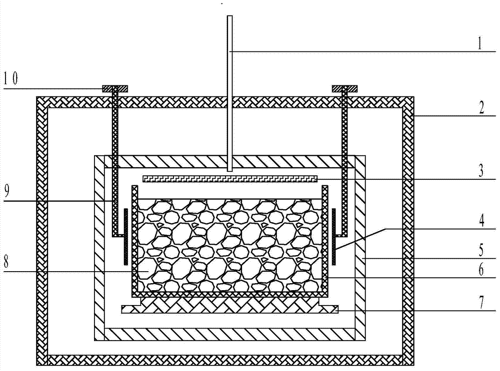
[0019] 1. Loading and vacuuming, start heating: put 450Kg of silicon material 8 into the quartz crucible 6, evacuate to 0.5Pa, pass argon gas through the vent 1 as a protective gas, and turn on the top heater 3 and the side heater 4 heating, the side heater 4 is equidistantly installed with 3 heat conduction rods 9 along the surrounding direction, the upper end of the heat conduction rod 9 is fixedly installed with the electrode rod 10 on the outer top of the furnace body 2, and the heat conduction rod 9 drives the side heater 4 on the quartz The crucible 6 reciprocates from the middle to the bottom at a speed of 80mm / min. After 5 hours of movement, the temperature of the silicon material 8 gradually reaches 1550°C.

[0020] 2. Melting stage: keep the pressure inside the furnace body 2 at 40KPa, keep the temperature of the silicon material 8 at 1550° C. and keep it warm for 8 hours until the silicon material 8 is completely melted. During this process, the side heater 4 recipr...

Embodiment 2

[0025] 1. Loading and vacuuming, start heating: put 500Kg of silicon material 8 into the quartz crucible 6, evacuate to 0.7Pa, pass argon gas through the vent 1 as a protective gas, and turn on the top heater 3 and the side heater 4 heating, the side heater 4 is equidistantly installed with 6 heat conduction rods 9 along the surrounding direction, the upper end of the heat conduction rod 9 is fixedly installed with the electrode rod 10 on the outer top of the furnace body 2, and the heat conduction rod 9 drives the side heater 4 on the quartz The crucible 6 reciprocates from the middle to the bottom at a speed of 150mm / min. After 6 hours of movement, the temperature of the silicon material 8 gradually reaches 1555°C.

[0026] 2. Melting stage: keep the pressure inside the furnace body 2 at 50KPa, keep the temperature of the silicon material 8 at 1555° C. and keep it warm for 10 hours until the silicon material 8 is completely melted. During this process, the side heater 4 reci...

Embodiment 3

[0031] 1. Loading and vacuuming, start heating: put 550Kg of silicon material 8 into the quartz crucible 6, evacuate to 1Pa, pass argon gas through the vent 1 as a protective gas, and turn on the top heater 3 and the side heater 4 Heating, the side heater 4 is equidistantly installed with 9 heat conduction rods 9 along the surrounding direction, the upper end of the heat conduction rod 9 is fixedly installed with the electrode rod 10 on the outer top of the furnace body 2, and the heat conduction rod 9 drives the side heater 4 in the quartz crucible The middle part of 6 moves back and forth between the lower part at a speed of 250mm / min. After 8 hours of movement, the temperature of silicon material 8 gradually reaches 1560°C.

[0032] 2. Melting stage: keep the pressure inside the furnace body 2 at 60KPa, keep the temperature of the silicon material 8 at 1560° C. and keep it warm for 12 hours until the silicon material 8 is completely melted. During this process, the side hea...


PUM


Abstract

The invention belongs to the field of polycrystalline silicon ingots, and particularly relates to an ingot furnace with a movable side heater and an ingot production process. The ingot furnace comprises a furnace body, wherein a quartz crucible is arranged in the furnace body, the side heater and a heat-preserving carbon felt are sequentially wound the outer wall of the quartz crucible from inside to outside, a top heater is fixedly arranged above the quartz crucible, a heat exchange block is arranged below the quartz crucible, heat conducting bars are equidistantly arranged on the side heater along the winding direction, and the other ends of the heat conducting bars are fixedly connected with an electrode rod at the top of the outside of the furnace body. The process comprises the steps of feeding materials and vacuumizing, feeding argon gas so as to increase pressure, heating for melting silicon materials, growing crystals, annealing and preserving heat, and cooling, wherein in the steps of heating and silicon material melting, the side heater carries out a reciprocating motion in the vertical direction of the quartz crucible; in the step of crystal growth, the side heater is kept in the middle of the quartz crucible; in the step of annealing and heat preservation, the side heater is kept at the lower part of the quartz crucible. According to the invention, the ingot production cost can be reduced by 5%.

Description

technical field [0001] The invention belongs to the field of polysilicon ingot casting, in particular to an ingot furnace with a movable side heater and an ingot production process. Background technique [0002] Polycrystalline silicon is a form of elemental silicon. When molten elemental silicon solidifies under supercooled conditions, silicon atoms are arranged in the form of diamond lattices to form many crystal nuclei, and these nuclei grow into crystal grains with different crystal plane orientations. These crystal grains Joined together to form polysilicon. The process of producing solar photovoltaic products in the solar photovoltaic industry includes polycrystalline silicon ingots, cutting into pieces, making cells and packaging them into solar modules. It can be seen that polycrystalline silicon ingots are an important part of the solar photovoltaic industry and the first choice for the production of solar photovoltaic products. link. Among them, the polysilicon i...

Claims


Application Information

Patent Timeline
Patent Type & Authority Applications(China)
IPC IPC(8): C30B11/00C30B29/06
Inventor 王峰李鹏廷谭毅任世强熊华江安广野姜大川
Owner QINGDAO XINSHIJI SOLAR ENERGY TECH CO LTD
Learn More