
Tensile RTP and manufacturing method thereof

A manufacturing method, tensile technology, applied in the direction of pipes, rigid pipes, pipes/fittings/fittings, etc.

Inactive Publication Date: 2014-02-12
NANJING CHENGUANG COMPOSITE PIPE ENG CO LTD
View PDF7 Cites 11 Cited by
  • Summary
  • Abstract
  • Description
  • Claims
  • Application Information

AI Technical Summary

Problems solved by technology

At present, most of the pipelines used in offshore oil and gas pipelines, land interspersed inner pipes, offshore risers and ocean crossover pipelines are RTP pipes. However, the existing RTP pipes can only bear a small amount of instantaneous axial tension, and their tensile capacity is far more If it is less than the use requirements specified above, moreover, when the RTP pipe is subjected to axial tension, the winding balance angle of its reinforcement tape will become smaller, and the pipe will shrink radially, thereby reducing the pressure bearing capacity and service life of the pipe

Method used


Image

  • Tensile RTP and manufacturing method thereof
  • Tensile RTP and manufacturing method thereof
  • Tensile RTP and manufacturing method thereof

Examples


Embodiment 1

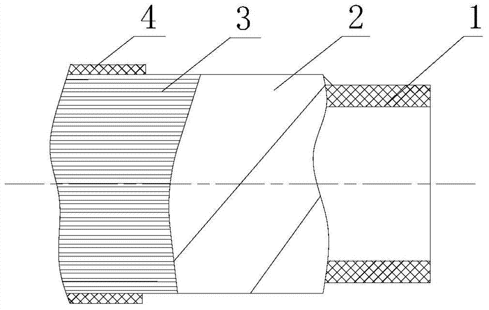
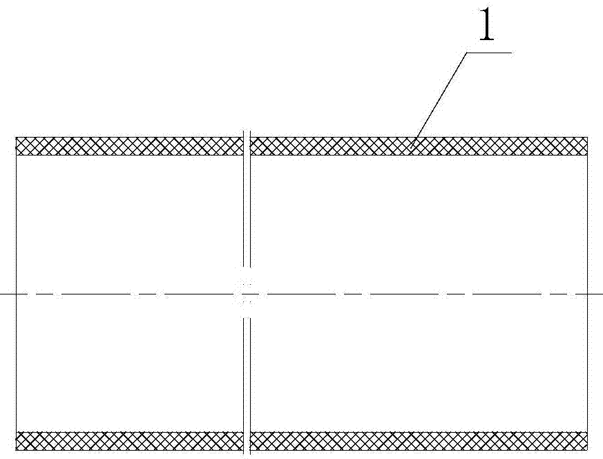
[0031] The tensile RTP pipe of the present embodiment has a structure such as figure 1 and figure 2 As shown, it includes the inner tube 1 and the reinforcement layer 2 wound on the inner tube 1. The reinforcement layer 2 is composed of two winding tapes wound on the outer wall of the inner tube 1 from opposite directions at a predetermined winding angle, wherein the winding angle is 54.7 °. The reinforcing layer 2 wraps the protective layer 4, and a tensile layer 3 is provided between the reinforcing layer 2 and the protective layer 4. The tensile layer 3 is composed of a group of pre-tensioned axial fiber ropes 8 uniformly distributed in the circumferential direction. The fiber ropes 8 Pre-tensioned by a tensioner, the pre-tensioned stress of the fiber rope 8 is 200 Newtons, and the pre-tensioned fiber rope 8 is evenly arranged on the outer surface of the reinforcement layer 2 along the axial direction of the pipeline through the pay-off frame 5, and the pre-tensioned Th...

Embodiment 2

[0035] The difference between this embodiment and Embodiment 1 is that the reinforcing layer 2 is composed of two winding tapes wound on the outer wall of the inner tube 1 from opposite directions at a predetermined winding angle, wherein the winding angle is 50°; the tensile layer is formed The fiber rope 8 of 3 is pre-tensioned by the tensioner, the pre-tension stress of the fiber rope 8 is 180 Newton, and the pre-tensioned fiber rope 8 is evenly arranged on the reinforcement layer 2 along the pipeline axis direction through the pay-off frame 5 The outer surface, and the circumferential interval of the pretensioned fiber rope 8 is 6mm, so that the protective layer 4 of the RTP pipe can be bonded to the reinforcing layer 2, and the tensile layer 3 can better withstand the axial pressure.

[0036] In the tensile RTP pipe manufacturing method of this embodiment, a spiral winding machine is used to wind two high-strength winding tapes from opposite directions at a winding angle o...

Embodiment 3

[0038] The difference between this embodiment and Embodiment 1 is that the reinforcement layer 2 is composed of two winding tapes wound on the outer wall of the inner tube 1 from opposite directions at a predetermined winding angle, wherein the winding angle is 60°; the tensile layer is formed The fiber rope 8 of 3 is pre-tensioned by a tensioner, and the pre-tension stress of the fiber rope 8 is 220 Newtons. The pre-tensioned fiber rope 8 is evenly arranged on the reinforcement layer 2 along the pipeline axis direction through the pay-off rack 5 The outer surface, and the circumferential interval of the pretensioned fiber rope 8 is 2mm, so that the protective layer 4 of the RTP pipe can be bonded to the reinforcing layer 2, and the tensile layer 3 can better withstand the axial pressure.

[0039] In the tensile RTP pipe manufacturing method of this embodiment, a spiral winding machine is used to wind two high-strength winding tapes on the outer wall of the inner pipe 1 from op...


PUM

PropertyMeasurementUnit
densityaaaaaaaaaa

Abstract

The invention relates to a tensile RTP and a manufacturing method of the tensile RTP. The pipe comprises an inner pipe and a reinforcing layer wound on the inner pipe, the reinforcing layer is wrapped by a protective layer, the reinforcing layer is composed of two winding straps which are wound on the outer wall of the inner pipe in the opposite directions of turning at preset winding angles, a tensile layer is arranged between the reinforcing layer and the protective layer, and the tensile layer is composed of a set of fiber ropes which are evenly distributed in the circumferential direction and are pre-tensioned in the axial direction. Raw materials are placed into an inner pipe extruder to be extruded and cooled for being sized to form the inner pipe, the two high-strength winding straps are wound on the outer wall of the inner pipe in the opposite directions of turning according to the preset winding angles to form the reinforcing layer, the set of fiber ropes are evenly arranged on the outer surface of the reinforcing layer in the direction of the axis of the pipeline after being pre-tensioned to form the tensile layer, raw materials are placed into an outer pipe extruder to be extruded so as to wrap the tensile layer to form the protective layer, and then online continuous production is achieved through coiling. The tensile RTP has the advantages of being high in tensile property and in flexibility, resistant to high temperature and corrosion, safe, reliable and the like, the RTP is formed at one time according to the manufacturing technology, the production period is short, and the production efficiency is high.

Description

technical field [0001] The invention relates to an RTP pipe, in particular to a tensile RTP pipe used for insertion, and also relates to a manufacturing method thereof, which belongs to the technical field of fluid delivery pipelines. Background technique [0002] The existing interspersed RTP pipes (also known as reinforced thermoplastic pipes) mainly insert high-density polyethylene pipes into the old pipes that need to be repaired, use the rigidity and strength of the old pipes as a load-bearing structure, and use high-density polyethylene pipes It has the characteristics of corrosion resistance, wear resistance, and penetration resistance, forming a "pipe-in-pipe" composite structure, so that the repaired pipeline has the comprehensive performance of steel pipe and high-density polyethylene. This method has low cleaning requirements for old pipelines, reduces pigging time and investment, not only has a short construction period and low cost, but also realizes long-dista...

Claims


Application Information

Patent Timeline
Patent Type & Authority Applications(China)
IPC IPC(8): F16L9/14B29C47/00B29C47/02B29C53/56
CPCF16L9/16B29B11/16B29C48/09B29C48/15B29C48/18F16L58/1036
Inventor 刘强季明慧荆祥海毛杰吴勇路勇陆建权吴海波郁蓉蓉
Owner NANJING CHENGUANG COMPOSITE PIPE ENG CO LTD
Learn More