Ultra-thin encoder of permanent magnet servo high-speed motor
What is Al technical title?
Al technical title is built by PatSnap Al team. It summarizes the technical point description of the patent document.
A high-speed motor and encoder technology, applied in the field of encoders, can solve the problems of irreplaceable, large installation space, inconvenient and fast installation and adjustment, etc., and achieves high installation and positioning accuracy, small installation space, and convenient and fast installation and adjustment. Effect
Inactive Publication Date: 2014-02-12
CHANGCHUN RONGDE OPTICS
View PDF0 Cites 3 Cited by
Summary
Abstract
Description
Claims
Application Information
AI Technical Summary
This helps you quickly interpret patents by identifying the three key elements:
Problems solved by technology
Method used
Benefits of technology
Problems solved by technology
[0004] Due to the unreasonable structure of the traditional encoder, that is, the installation of the luminous tube is fixed by the circuit board, there are many shortcomings and deficiencies, which are specifically manifested in: ①. The luminous tube is not fixed firmly and unstable; ②. The overall structure of the encoder Not compact, the installation space is large, the installation and adjustment are not convenient and fast enough, ③, the weight is large, the thickness is large, the cost is high, and it does not meet the needs of modern industry requirements for small size and more powerful functions, and cannot replace high-end foreign similar products
Method used
Image
Click on the blue label to locate the original text in one second.
Reading with bidirectional positioning of images and text.
Examples
Embodiment Construction
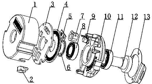
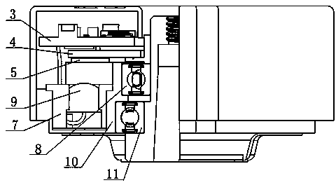
[0015] attached by figure 1 , 2 As shown: the encoder includes a casing 1, a rubber molded wire sheath 2, a circuit board with electrical components 3, a moving grating 4, a fixed grating 5, a moving grating seat 6, a light-emitting diode sleeve 7, and a first bearing 8 , light emitting diode 9, main body support 10, second bearing 11, hollow shaft 12 and plate spring 13, described circuit board 3 with electrical components, moving grating 4, fixed grating 5, moving grating seat 6, light emitting diode The pipe sleeve 7, the first bearing 8, the light emitting diode 9, the main body support 10, the second bearing [11 and the hollow shaft 12 are assembled to form the main body of the encoder, the shell 1 is set on the outside of the main body of the encoder, and the leaf spring 13 is arranged on the Below the main body of the device, the rubber molding grommet 2 is arranged on the side of the casing 1, and the light-emitting diode 9 is set in the light-emitting diode tube cove...
PUM
Abstract
The invention relates to an encoder, also named speed and displacement sensor, in particular to an ultra-thin encoder of a permanent magnet servo high-speed motor. The ultra-thin encoder comprises a shell, a rubber-formed wire protecting bushing, a circuit board provided with electric elements, a movable raster, a fixed raster, a movable raster base, a first bearing, a light emitting diode, a main support, a second bearing, a hollow shaft and a blade spring. The ultra-thin encoder of the permanent magnet servo high-speed motor is characterized in that the ultra-thin encoder further comprises a light emitting diode sleeve, the light emitting diode is sleeved with the light emitting diode sleeve, and the light emitting diode sleeve is arranged on the main support. Due to the fact that the light emitting diode of the encoder is installed in an embedded mode, space is saved, production positioning accuracy is improved, and the problem that in the prior art, a light emitting diode is fixed by means of a circuit board, and fixation is unstable and unreliable is solved. The ultra-thin encoder of the permanent magnet servo high-speed motor is compact, small in occupied space, simple, reasonable, and convenient and fast to assembly and adjust. Compared with existing encoders, the ultra-thin encoder of the permanent magnet servo high-speed motor is lighter, thinner and lower in cost. The installation space is small, and requirements of the modern industry for smaller size and more powerful function are met.
Description
technical field [0001] The invention relates to an encoder, also known as a speed and displacement sensor, in particular to an ultra-thin encoder for a permanent magnet servo high-speed motor. Background technique [0002] The servo motor encoder is a sensor installed on the servo motor to measure the position of the magnetic pole and the rotation angle and speed of the servo motor. The basic function of the servo encoder is the same as that of the ordinary encoder. The rotary incremental encoder outputs when rotating Pulse, the position is calculated by the counting device. When the encoder does not move or the power is cut off, it relies on the internal memory of the counting device to remember the position. In addition, the servo encoder is different from the ordinary encoder, that is Most of the servo motors are synchronous motors. When the synchronous motor is started, the magnetic pole position of the rotor needs to be known, so that the servo motor can be started with...
Claims
Application Information
Patent Timeline
Application Date:The date an application was filed.
Publication Date:The date a patent or application was officially published.
First Publication Date:The earliest publication date of a patent with the same application number.
Issue Date:Publication date of the patent grant document.
PCT Entry Date:The Entry date of PCT National Phase.
Estimated Expiry Date:The statutory expiry date of a patent right according to the Patent Law, and it is the longest term of protection that the patent right can achieve without the termination of the patent right due to other reasons(Term extension factor has been taken into account ).
Invalid Date:Actual expiry date is based on effective date or publication date of legal transaction data of invalid patent.