

Method for detecting resonant wavelength shift of integrated resonant ring
A technology of integrating resonant ring and resonant wavelength, applied in the field of integrated optical sensing, can solve the problems of affecting the detection accuracy of resonant wavelength, affecting the detection accuracy, etc., so as to improve the detection accuracy and stability, improve the detection accuracy and improve the stability. Effect
- Summary
- Abstract
- Description
- Claims
- Application Information
AI Technical Summary
Problems solved by technology
Method used
Image

Examples
Embodiment 2
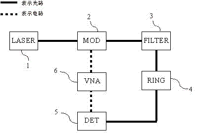
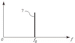
[0023] Embodiment 2: Laser 1 outputs a single-frequency laser 7, the frequency is , and its spectrum is as image 3 shown. This laser light passes through an intensity or phase modulator 2 . The intensity or phase modulator is driven by a network analyzer 6 . The output frequency of the network analyzer is between 1GHz and 60GHz. The spectrum of the output light after the laser is modulated by the modulator is as follows: Figure 4 shown. In addition to the original input laser light 7, the modulated optical signal will also contain two sideband lights 9 and 8, whose frequencies are and , respectively. After that, the optical signal will be input to filter 3 . This filter will filter out frequencies as sideband light 9, the output spectrum is as Figure 6 shown. The optical signal after passing the filter will be input to the integrated resonant ring 4, and then converted into an electrical signal by the detector 5, and acquired by the network analyzer 6 to analyze the ...
Embodiment 3
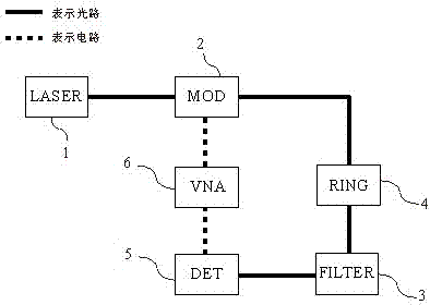
[0024] Embodiment 3: as figure 2 As shown, the laser 1 outputs a single-frequency laser 7, the frequency is , and its spectrum is as image 3 shown. This laser light passes through an intensity or phase modulator 2 . The intensity or phase modulator is driven by a network analyzer 6 . The output frequency of the network analyzer is between 1GHz and 60GHz. The spectrum of the output light after the laser is modulated by the modulator is as follows: Figure 4 shown. In addition to the original input laser light 7, the modulated optical signal will also contain two sideband lights 9 and 8, whose frequencies are and , respectively. Afterwards, the optical signal will be input to the integrated resonant ring 4 and then to the filter 3 . This filter will filter out frequencies as sideband light 8, the output spectrum is as Figure 5 shown. The optical signal after passing the filter will be converted into an electrical signal by the detector 5 and acquired by the network an...
Embodiment 4
[0025] Embodiment 4: Laser 1 outputs a single-frequency laser 7, the frequency is , and its spectrum is as image 3 shown. This laser light passes through an intensity or phase modulator 2 . The intensity or phase modulator is driven by a network analyzer 6 . The output frequency of the network analyzer is between 1GHz and 60GHz. The spectrum of the output light after the laser is modulated by the modulator is as follows: Figure 4 shown. In addition to the original input laser light 7, the modulated optical signal will also contain two sideband lights 9 and 8, whose frequencies are and , respectively. Afterwards, the optical signal will be input to the integrated resonant ring 4 and then to the filter 3 . This filter will filter out frequencies as sideband light 9, the output spectrum is as Figure 6 shown. The optical signal after passing the filter will be converted into an electrical signal by the detector 5 and acquired by the network analyzer 6 to analyze the phas...
PUM
 Abstract
Description
Claims
Application Information