An on-line monitoring system and monitoring method for the temperature of the intermediate joint of buried cables

A technology of cable intermediate joint and monitoring system, which is applied to thermometers, thermometers using electrical/magnetic components directly sensitive to heat, signal transmission systems, etc., can solve the problems of difficult installation and maintenance, high cost, and difficulty in power supply. Achieve the effect of eliminating potential safety hazards and unreliability, low cost, and eliminating the need for communication cables

Active Publication Date: 2016-04-20
STATE GRID CORP OF CHINA +2
View PDF9 Cites 0 Cited by
  • Summary
  • Abstract
  • Description
  • Claims
  • Application Information

AI Technical Summary

Problems solved by technology

[0004] In view of the problems of the existing on-line monitoring system for cable intermediate joints, such as high cost, difficulty in power supply, and difficulty in installation and maintenance, the purpose of the present invention is to provide an on-line temperature monitoring system for buried cable intermediate joints, and another purpose is to provide an underground The online monitoring method for the temperature of the cable intermediate joint, the invention uses a wireless sensor to measure the temperature of the outer skin of the cable intermediate joint, transmits the monitoring data in a wireless manner, and uses a thermoelectric generator and an energy collector to convert the temperature difference into electrical energy to supply power to the wireless sensor, with low cost , maintenance-free, easy installation, high degree of safety, etc.

Method used


Image

  • An on-line monitoring system and monitoring method for the temperature of the intermediate joint of buried cables
  • An on-line monitoring system and monitoring method for the temperature of the intermediate joint of buried cables

Examples


Embodiment Construction

[0036] The specific implementation manners of the present invention will be further described in detail below in conjunction with the accompanying drawings.

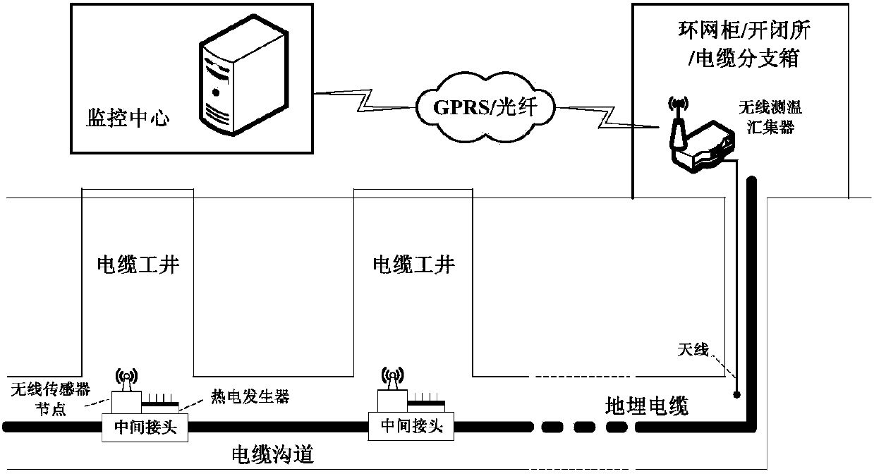
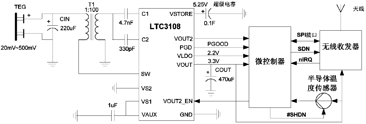
[0037] Aiming at the problems of the existing on-line monitoring system for cable intermediate joints such as high cost, difficult power supply, difficult installation and maintenance, etc., the present invention uses a thermoelectric generator and an energy collector to convert temperature difference into electric energy to supply power for wireless sensors, and at the same time collect monitoring data wirelessly ; The wireless sensor works in a low-power mode, thereby reducing the power consumption of the entire monitoring system.

[0038] The structural diagram of the buried cable intermediate joint temperature on-line monitoring system provided by the present invention is as follows figure 1As shown, the online temperature monitoring system includes at least one wireless sensor node, a thermoelectric generator (TEG)...


PUM


Abstract

The invention relates to an on-line temperature monitoring system and method for power cables, in particular to an on-line temperature monitoring system and method for intermediate joints of a buried cable. The monitoring system is composed of wireless sensor nodes, TEGs, a wireless temperature measurement concentrator and a monitor center, wherein the intermediate joints of the buried cable are located below cable work wells; the wireless sensor nodes and the TEGs are installed on the outer surfaces of the intermediate joints of the buried cable; the wireless temperature measurement concentrator is installed in a switching station or a ring main unit or a cable branch box at a cable terminal or a branch joint; an antenna of the wireless temperature measurement concentrator extends into a cable channel to collect monitor data of the wireless sensor nodes and send the monitor data to the monitor center through a GPRS or an optical fiber. According to the on-line temperature monitoring system and method for the intermediate joints of the buried cable, the TEGs and an energy collector are adopted to convert temperature difference into electric energy to be supplied for a wireless sensor, and at the same time, the monitor data are collected in a wireless mode; the wireless sensor nodes work in a low-power dissipation mode, and therefore the power dissipation of the whole monitoring system is reduced.

Description

technical field [0001] The invention relates to an on-line monitoring system and a monitoring method for the temperature of a power cable, in particular to an on-line monitoring system and a monitoring method for the temperature of an intermediate joint of an underground cable. Background technique [0002] With urbanization and the development of urban power grids, power cables have been widely used, and the average annual growth rate in my country has reached 35%. With the increase in the number of cables used and the increase in power transmission capacity, once a fault occurs, the damage will be serious, so the operational reliability of power cables has received more and more attention. Through the investigation of the failure rate of power cables in major cities across the country, it is found that within 1 to 5 years of the initial operation of the cable and 5 to 25 years after it is put into operation, the failure of power cable accessories (including branch joints, ...

Claims


Application Information

Patent Timeline
Patent Type & Authority Patents(China)
IPC IPC(8): G01K7/00G08C17/02
Inventor 盛万兴孙军平李玉凌李二霞史常凯姜建钊许保平樊勇华孙智涛周自强徐晓华江明强
Owner STATE GRID CORP OF CHINA
Why Eureka
Try Eureka