Dynamic real-time compensation system for positioning errors of numerical-control machine tool

A positioning error, CNC machine tool technology, applied in the field of compensation systems, can solve problems such as increasing application costs, inability to model intelligent judgment and adjustment, and inability to apply machine tool production conditions, etc., to improve the design level and overcome intelligent adjustment and parameters. Corrected effect

Inactive Publication Date: 2014-02-12
上海睿涛信息科技有限公司
View PDF1 Cites 44 Cited by
  • Summary
  • Abstract
  • Description
  • Claims
  • Application Information

AI Technical Summary

Problems solved by technology

According to the structure and principle of the real-time compensation device provided by the invention, a machine tool positioning error compensation device integrating a calculation processing module, a temperature sensor acquisition and transmission module, and a numerical control interface control module is mainly discussed. The data interaction between PMCs is used to realize the compensation of positioning errors. However, this invention also uses the preset mathematical model to calculate the compensation value, and it is impossible to intelligently judge and adjust the model in actual use. Therefore, the invention The compensation device provided is also not applicable to the actual production conditions of the machine tool
In addition, the compensation device uses the communication method with the PMC of the machine tool to realize data interaction, so it needs to occupy more I / O port resources. When there is a lot of data to be interacted with, it is necessary to expand the I / O module to achieve. Increased application cost

Method used


Image

  • Dynamic real-time compensation system for positioning errors of numerical-control machine tool
  • Dynamic real-time compensation system for positioning errors of numerical-control machine tool

Examples


Embodiment Construction

[0026] Embodiments of the present invention will be described below in conjunction with the accompanying drawings. This embodiment is implemented on the premise of the technical solution of the invention, and detailed implementation methods and specific processes are given, but the protection scope of the present invention is not limited to the following embodiments.

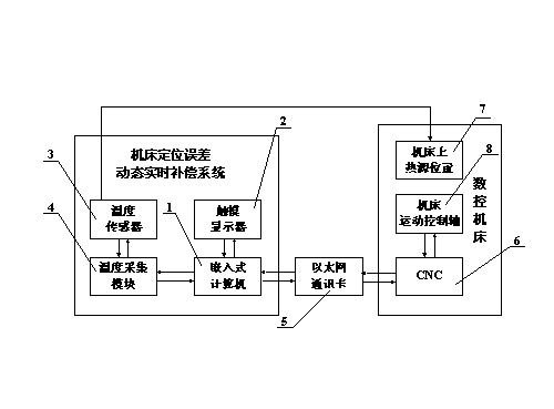
[0027] The hardware system structure of the error real-time compensation system of the present invention is as follows: figure 1 As shown, it includes: embedded computer 1, touch display 2, temperature sensor 3, temperature acquisition module 4, network communication card 5, CNC machine tool 6, heat source position 7 on the machine tool, and machine tool motion control axis 8.

[0028] The specific implementation process of the hardware system of this embodiment is as follows:

[0029] 1. The embedded computer 1 is connected with the touch display 2 through the video cable and the USB cable, connected with the ...


PUM


Abstract

The invention discloses a dynamic real-time compensation system for positioning errors of a numerical-control machine tool. The system comprises an error compensation hardware system and a compensation software platform based on network data interaction. The hardware system serves as a carrier and an executing part of compensation software and is used for achieving connection, communication, data storage and human-computer interaction between all functional modules. A programming mode oriented to objects is adopted for the software system, the software system has data interaction with CNC through an Ethernet, and therefore temperature signals can be collected and preprocessed, a positioning error mathematical model can be automatically established, and real-time calculation of the positioning errors, the intelligent model adjusting function, and training and optimizing on a self-learning model can be achieved. Due to cooperative work of the software system and the hardware system, the dynamic real-time compensation for the positioning errors of the numerical-control machine tool is achieved. The compensation system for the positioning errors is easy to operate, wide in application range and capable of meeting positioning error compensation requirements of various numerical-control machine tools and has great practical and commercialized application significance in improving machining accuracy of the numerical-control machine tools.

Description

technical field [0001] The invention relates to a compensation system in the technical field of error compensation of a numerical control machine tool, specifically, a dynamic real-time compensation system for positioning errors of a numerical control machine tool. Background technique [0002] After years of continuous development, my country's machine tool industry has made great leaps. In terms of the overall production scale, my country's annual machine tool production has reached the same level as the major machine tool producing countries. But as far as the technical level of CNC machine tools is concerned, it is only ranked in the second echelon in the world. At present, the CNC machine tools produced in my country account for about 35% of the domestic CNC machine tool market share, and the rest need to be imported from abroad, especially in the high-end CNC machine tool market, most of which can only be imported from foreign machine tool production powerhouses. The ...

Claims


Application Information

Patent Timeline
Patent Type & Authority Applications(China)
IPC IPC(8): G05B19/404
Inventor 姚晓栋
Owner 上海睿涛信息科技有限公司
Why Eureka
Try Eureka