Check patentability & draft patents in minutes with Patsnap Eureka AI!

An adjustable signal source circuit

A signal source and circuit technology, applied in electrical components and other directions, can solve the problems of high power consumption, inconvenient low-power system application, complex circuits, etc., and achieve the effects of low cost, strong stability and simple circuit structure.

Inactive Publication Date: 2016-08-31
昆山龙仕达电子材料有限公司
View PDF4 Cites 0 Cited by
  • Summary
  • Abstract
  • Description
  • Claims
  • Application Information

AI Technical Summary

Problems solved by technology

However, its circuit is complex and consumes a lot of power, which is not convenient for low-power system applications.

Method used


Image

  • An adjustable signal source circuit

Examples


Embodiment Construction

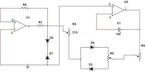
[0009] Such as figure 1 As shown, the present invention includes an operational amplifier, a resistor, a diode and a variable resistor. The output terminal of the first operational amplifier U1 is connected to the positive phase input terminal of the first operational amplifier U1 through the series connection of the first resistor R1 and the second resistor R2. One end of the first resistor R1 is connected to the anode of the second diode D2, the cathode of the second diode D2 is connected to the cathode of the third diode D1, and the anode of the third diode D1 is grounded; the first resistor R1 One end of the variable resistor R3 is connected to one end of the third resistor R3, the adjusting end of the first variable resistor R3 is connected to the positive pole of the fourth diode D4, and the positive pole of the fourth diode D4 is connected to the negative pole of the third diode D3, The anode of the third diode D3 is connected to the cathode of the fourth diode D4 throu...


PUM


Abstract

The invention discloses an adjustable signal source circuit, which includes an operational amplifier, a resistor, a diode and a variable resistor. The invention uses a two-stage operational amplifier and a voltage-stabilizing diode to form a stable waveform output, and adjusts the output by adjusting a sliding rheostat. The amplitude and frequency of the signal, the circuit structure of the invention is simple, the cost is low, the stability is strong, and it is suitable for small laboratories.

Description

technical field [0001] The invention relates to a signal source circuit, in particular to an adjustable signal source circuit. Background technique [0002] The signal source circuit is the core unit circuit of an analog integrated circuit, especially in power management chips, the signal source often determines the performance indicators of such chips, and it is widely used in various analog circuits such as oscillators, phase-locked loops, and data converters. and digital-analog hybrid integrated circuits. However, its circuit is complex and consumes a lot of power, which is not convenient for low-power system applications. [0003] Therefore need a kind of new technical scheme to solve the above problems. Contents of the invention [0004] Purpose of the invention: Aiming at the problems and deficiencies in the prior art above, the purpose of the invention is to provide an adjustable signal source circuit with low cost and stable waveform output. [0005] Technical s...

Claims


Application Information

Patent Timeline
Patent Type & Authority Patents(China)
IPC IPC(8): H03B28/00
Inventor 王火明
Owner 昆山龙仕达电子材料有限公司
Features
  • R&D
  • Intellectual Property
  • Life Sciences
  • Materials
  • Tech Scout
  • Unparalleled Data Quality
  • Higher Quality Content
  • 60% Fewer Hallucinations
Learn More