A self cleaning gas-liquid separator for serial or parallel collection of liquid fractions

A technology for collecting containers and liquids, which is used in solid adsorbent liquid separation, separation methods, material separation, etc., and can solve problems such as changes in mobile phase and discharge time.

Active Publication Date: 2014-02-12
AGILENT TECH INC
View PDF5 Cites 9 Cited by
  • Summary
  • Abstract
  • Description
  • Claims
  • Application Information

AI Technical Summary

Problems solved by technology

Most of the existing collectors have the disadvantage that the drain time varies significantly depending on

Method used


Image

  • A self cleaning gas-liquid separator for serial or parallel collection of liquid fractions
  • A self cleaning gas-liquid separator for serial or parallel collection of liquid fractions
  • A self cleaning gas-liquid separator for serial or parallel collection of liquid fractions

Examples


other Embodiment approach

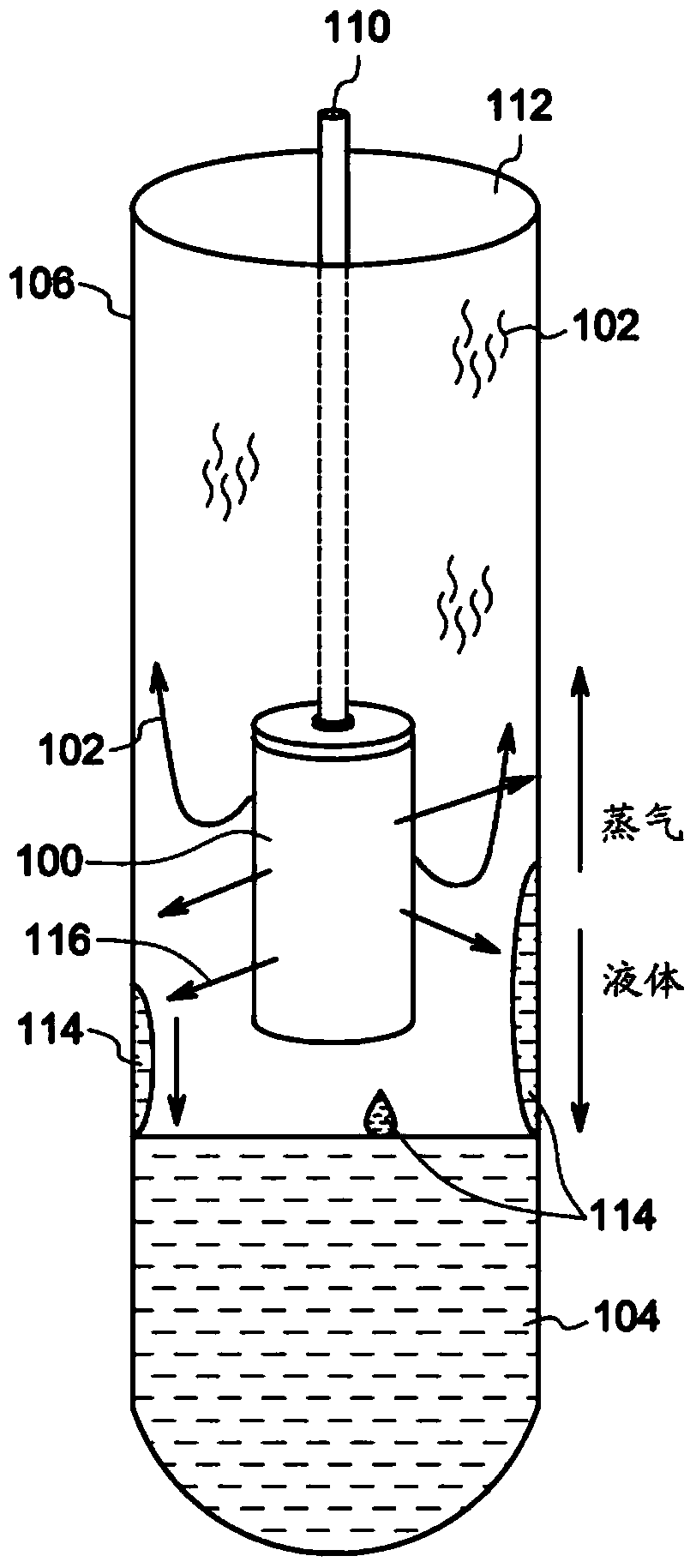
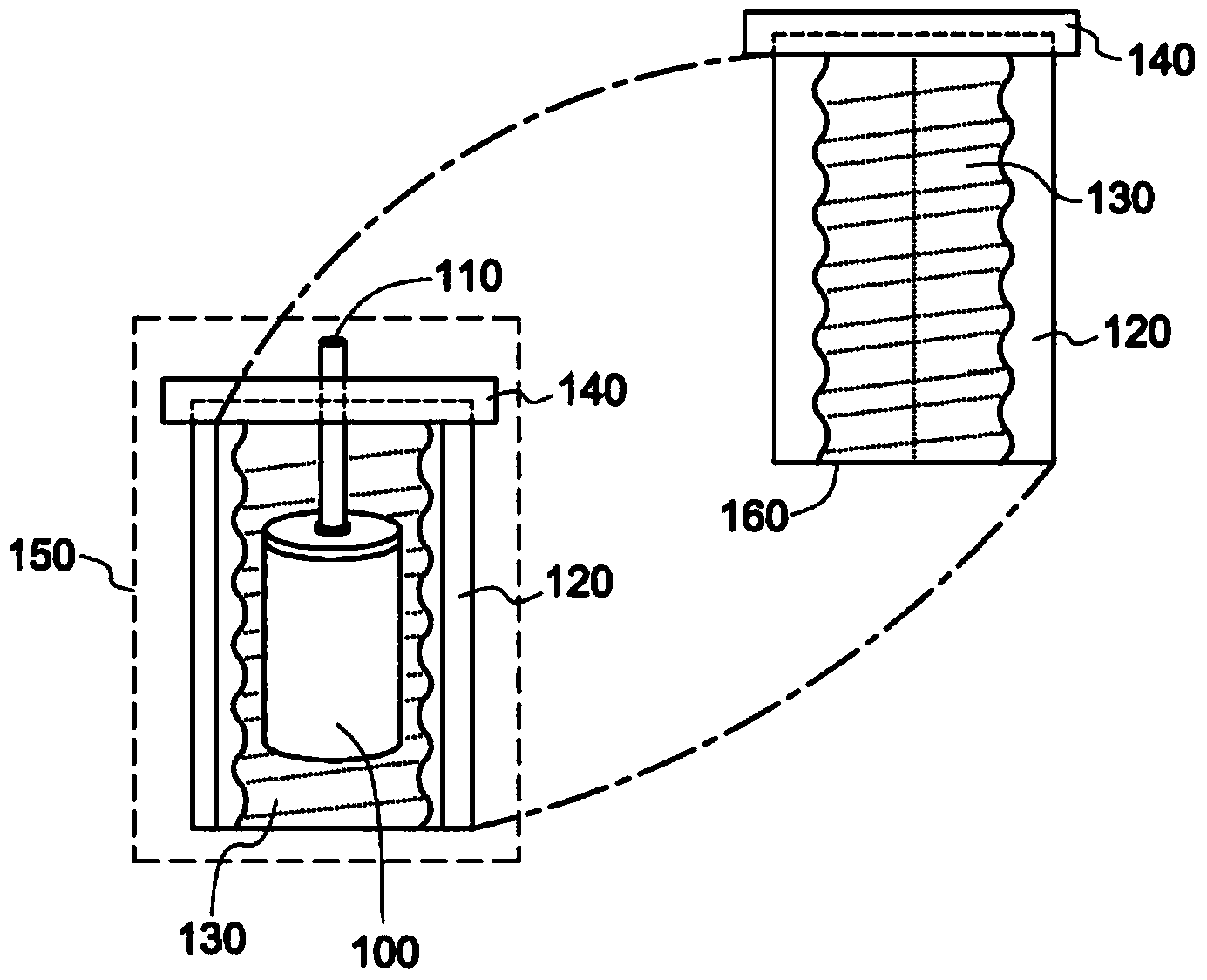
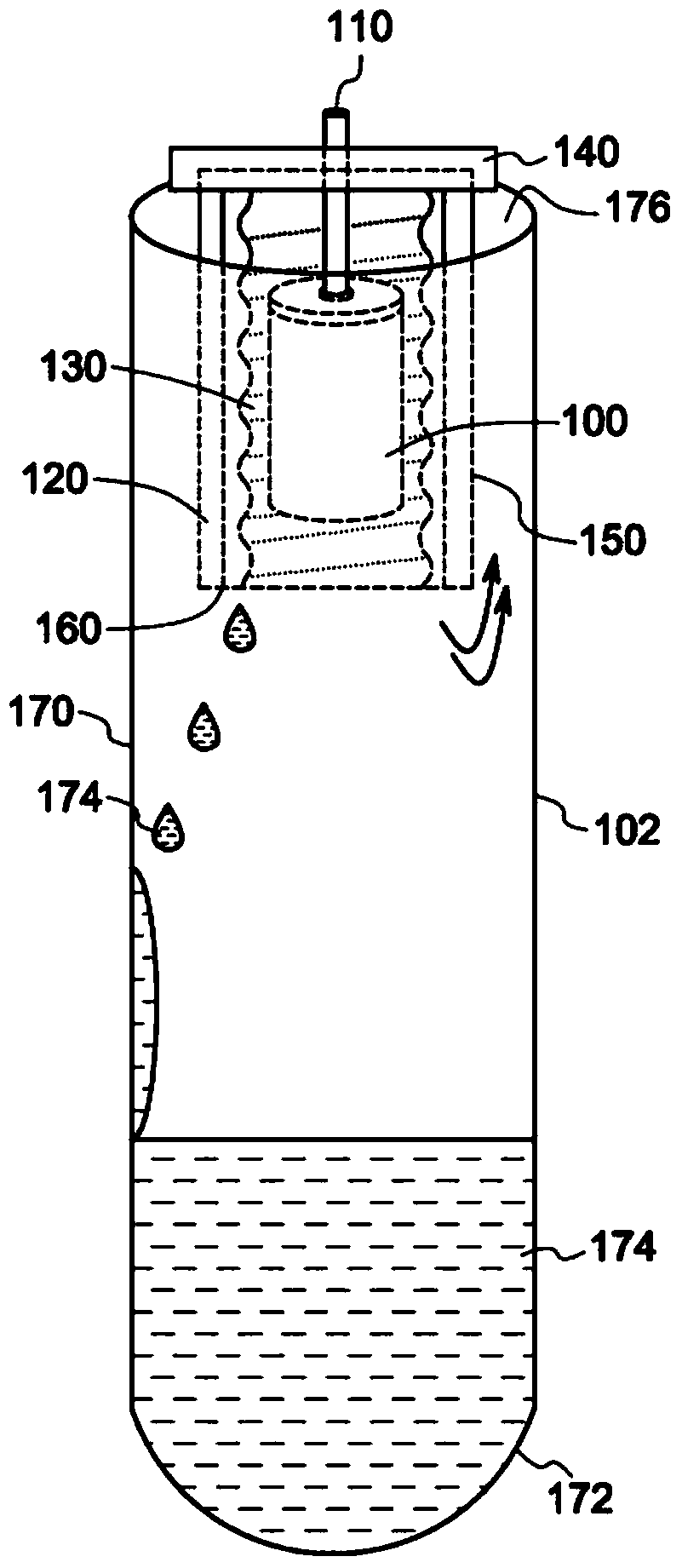
[0046] Other embodiments provide additional rinse capability via a syringe pump 550 connected by a flow path to the syringe valve 560 and circuit 570 . In its normal state, circuit 570 is connected between syringe pump 550 and waste 548 via flow path 546, wherein circuit 570 may be filled with a suitable wash solvent. When the end of the peak is detected, valve 560 is switched to pass the contents of circuit 570 to separator assembly 150 as a flood wash step. This behavior should adequately limit any carryover from prior samples. After a short time, the valve 560 is switched back and the circuit is filled again. It will be appreciated that the pump 550 could be replaced by a variety of other pump types, or even a pressurized wash solvent reservoir and solenoid valve to complete loop filling.

[0047] Figure 7 [0009] Another embodiment in ® includes an active discharge pumping system, which is the subject of a separate pending patent application assigned to the same assigne...


PUM


Abstract

An apparatus, process, and system are disclosed that effectively provide separation of a combined gas/liquid flow stream into its separated gas and liquid factions. The invention is primarily directed to the fields of preparative supercritical fluid chromatography [SFC] and supercritical fluid extraction [SFE], but will have other utilization and applicability where phases of dramatically different density, viscosity and volumetric flow require separation.

Description

technical field [0001] The present invention relates generally to the technical fields of supercritical fluid chromatography and supercritical fluid extraction, but includes alternative utilization and applications requiring the separation of phases having significantly different densities, viscosities and volume flows. Background technique [0002] Supercritical fluid extraction (SFE) and preparative ("Prep") supercritical fluid chromatography (SFC) each require equipment and methods for collecting liquid fractions from the endpoint of a flow system. The main components of supercritical fluid (SF) mobile phases include highly compressed gases such as carbon dioxide (CO2) and liquid organic co-solvents, or modifiers. For collection, the mobile phase must be brought to near ambient pressure where the CO2 component is an expanded gas with a volume up to 500 times the volume of the compressed phase. The CO2 entrains a much smaller volume, residual compound of interest comprisi...

Claims


Application Information

Patent Timeline
IPC IPC(8): B01D15/40B01D15/08B01D11/00
CPCB01D11/0292G01N30/84B01D46/0082G01N2030/8411B01D11/0407G01N30/80B01D15/247B01D15/40B01D46/0031B01D11/0203B01D46/003B01D46/79
Inventor K.福格尔曼T.A.伯格E.E.维克福斯
Owner AGILENT TECH INC
Why Eureka
Try Eureka